Traffic loading is a critical factor in the design and assessment of road bridges, directly influencing structural safety, durability, and serviceability. The European standard EN 1991-2 provides a comprehensive framework for defining traffic loads across various bridge types and traffic scenarios. By adopting EN 1991-2, engineers can design bridges that meet stringent safety and reliability criteria while accommodating diverse traffic conditions across European continent and beyond.
Scope of EN 1991-2
The scope of EN 1991-2 is comprehensive, extending beyond road bridges to encompass railway bridges and pedestrian footbridges. This standard specifies the traffic loading models and associated dynamic effects that must be considered in the structural design of bridges subjected to vehicular, rail, and pedestrian traffic.
The loading provisions outlined in EN 1991-2 are intended primarily for the design of new bridge structures, including not only the main superstructure but also critical substructure components such as: piers and abutments, Upstand walls and wing walls, Flank walls, Bridge decks and parapets, and foundations and transition zones
Scope of this Guide
Of all the traffic loads covered in EN 1991-2, the discussion in this article is limited to vehicular traffic loading on road bridges. This includes vertical load models and their dynamic effects, horizontal loads due to traffic actions (acceleration and braking), and their conditions of mutual combination.
Before diving into different types of load models presented in the standard, we shall first discuss a few terms associated with Bridge design and traffic loading.
Important Key Terms
These are key terms relevant to understanding traffic load on bridges
Carriageway: Carriage way is a part of road surface supported by single structures (deck, pier, etc.), which includes all physical traffic lanes, hard shoulders, hard strips and marker strips.
Notional Lane: Notional Lane is a strip of the carriageway, parallel to an edge of the carriageway, which is deemed to carry a line of cars and/or lorries. The notional lanes are defined during analytical modelling for the main purpose of assigning traffic load on bridges.
Remaining Area: Remaining area is the difference, where relevant, between the total area of the carriageway and the sum of the areas of the notional lanes
Wheel Load: Wheel load is the load exerted by a single wheel on the road surface. It is often half of the axle load.
Axle Load: Axle load is the combined load of two adjacent wheels that are consecutively loaded
Tandem system: Tandem system is an assembly of two consecutive axles considered to be simultaneously loaded
Abnormal Load: Vehicle load which may not be carried on a route without permission from the relevant authority
Division of Carriageway into Notional Lanes
To apply traffic load models on a bridge, the carriageway has to be divided into notional lanes and remaining area. The width w of the carriageway is measured between inner limits of vehicle restraint systems or between Kerbs. The minimum height of Kerbs should be defined by the national annex (75mm according to the UK National Annex), however the recommended value by the standard is 100mm
Where the carriageway on a bridge deck is physically divided into two parts separated by a central reservation, then:
- each part, including all hard shoulders or strips, should be separately divided into notional lanes if the parts are separated by a permanent road restraint system.
- the whole carriageway, central reservation included, should be divided into notional lanes if the parts are separated by a temporary road restraint system.
The carriage way width w is divided into the greatest possible integer number of notional lanes as depicted in table 4.1 of EN 1991-2 which is reproduced below
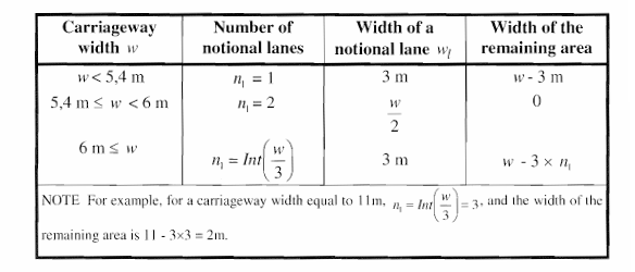
Numbering of Notional Lanes
- The locations of notional lanes should not be necessarily related to their numbering.
- The lanes are numbered 1,2,3, etc. in such a way that the lane giving the most unfavourable effect is Lane No. 1, the lane giving the second most unfavorable effect is Lane No. 2, etc.
- Where the carriageway consists of two separate parts on the same deck, only one numbering should be used for the whole carriageway.
- Where the carriageway consists of two separate parts on two independent decks, each part should be considered as a carriageway. Separate numbering should then be used for the design of each deck. If the two decks are supported by the same piers and/or abutments, there should be one numbering for the two parts together for the design of the piers and/or the abutments.
Traffic Loads
Loads on bridges due to traffic actions are loads induced by cars, trucks, lorries, special vehicles etc. These loads give rise to vertical and horizontal, static and dynamic forces. EN 1991-2 presents load models that have been calibrated such that they induce the same effects, including dynamic amplification (except for fatigue models which is not considered in this article), as actual traffic on bridges. These models are intended to represent the most unfavorable yet realistic traffic scenarios a bridge may experience during its service life.
Loading Classes
It is obvious that vehicle traffic characteristics can vary significantly from one bridge to another, influenced by factors such as: traffic composition (e.g., proportion of heavy vehicles like lorries), traffic density (e.g., average annual number of vehicles), operational conditions (e.g., frequency and duration of traffic jams), vehicle weights and axle load configurations, regulatory constraints. EN 1991-2 allows for this variable through adjustment factor α and β for load model 1 and load model 2 respectively.
Characteristics Values of Traffic Load Models for Vertical Loads
Characteristic loads are intended for the determination of road traffic effects associated with ultimate limit state verifications and with particular serviceability verifications. The load models for vertical traffic loads are enumerated below
Load Model 1
Load Model 2
Load Model 3
Load Model 4
-
Load Model 1 (LM1)
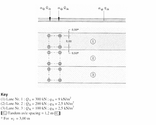
This consists of a double-axle concentrated load representing a tandem system, and uniformly distributed load (UDL) applicable to all bridges. It is intended to cover flowing, congested or traffic jam situations. It covers most of the effect of cars and heavy lorries. It should be used for general and local verifications.
The weight of each axle load (∝Q Qk) and magnitude of uniformly distributed load (∝Q qk) as applicable to each notional lane are given in table 4.2 of the standard which is reproduced below.

Rules Guiding Application of Load Model 1 to Bridges
- No more than one tandem system should be taken into account per notional lane.
- Only complete tandem systems should be taken into account.
- For the assessment of general effects, each tandem system should be assumed to travel centrally along the axes of notional lanes
- Each axle of the tandem system should be taken into account with two identical wheels, the load per wheel being therefore equal to 0.5∝Q Qk.
- The contact surface of each wheel should be taken as square and of side 0.40m
- The uniformly distributed loads should be applied only in the unfavorable parts of the influence surface, longitudinally and transversally.
- The values of adjustment factors ∝Qi, ∝qi, and ∝qr should be selected depending on the expected traffic and possibly on different classes of routes. In the absence of specification these factors should be taken equal to unity.
UK National Annex Approach to Load Model 1
- The UK National Annex allows load model 1 to be applicable to road length of more than 200m, it allows for length up to 1500m
- Adjustment factor for load model one is provided in Table NA.1 of the UK NA
-
Load Model 2 (LM2)
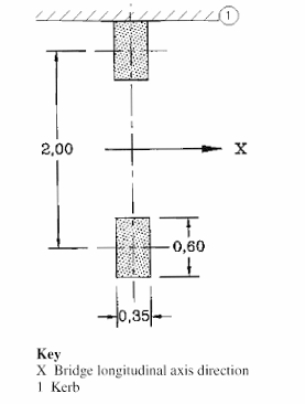
Load model two consist of single axle load of 400KN consisting of two wheels with specific contact areas of 0.35 x 0.65 m. it covers the dynamic effect of normal traffic on short structural members. It is used for local verification of short structural members of about 3 to 7m span. When relevant, only one wheel load of 200KN may be taken into account.
The axle load of load model 2 can be represented as shown below:
βQ Qk
Where:
βQ is the adjustment factor
Qk is 400KN
The UK National Annex Approach to Load Model 2
- The contact surface of each wheel in Load Model 2 should be taken as a square of sides 0.4m.
-
Load Model 3 (LM3)
This represents a series of axle loads representing special vehicles with abnormal loads. This type of vehicles typically travels on route designated by government for such abnormal loads. The load model is intended for general and local verifications. It should only be applied when expressly demanded by clients. A set of standardized special lorry are presented in the informative Appendix A of EN 1991-2.
UK National Annex approach to Load Model 3
The UK National Annex describes two groups of special vehicles, SV and SOV vehicles. More details about load models, dynamic amplification factor, and application of these special vehicles can be found in NA.2.16.1 to NA.2.16.4
-
Load Model 4 (LM4)
A crowd loading, intended only for general verifications. It is generally taken as 5KN/m². This crowd loading is particularly relevant for bridges located in or near towns if its effects are not covered by Load Model 1. It should only be used for transient design situation. It should be used as specified for an individual project, and only when required by the client.
Characteristic Values of Horizontal Traffic Loads
Horizontal loads on bridges includes loads due to breaking force, and acceleration.
Breaking and Acceleration Forces
The breaking force is represented by a longitudinal force, acting at the surfacing level of the carriageway. It should have a limited characteristic value of 900kN, and should be calculated as a fraction of the total maximum vertical loads due to LM1 applied to lane No. 1. Expression (4.6) of the standard gives formular to evaluate the breaking force which is rendered here as follows:
Q1k = 0.6∝Qi(2Q1k) + 0.10∝Qi q1k w1L
180∝Qi ≤ Q1k ≤ 900
Acceleration force should also be calculated using the same expression as for breaking force but in opposite direction.
Where:
L is length of the deck
2Q1k is the weight of the two axles of tandem system applied to lane No. 1
q1k is the density of the uniformly distributed load on lane No. 1
w is the width of lane No 1
∝Q1 is the adjustment factor
Centrifugal Force
The centrifugal force Qtk should be taken as a transverse force acting at the finished carriageway level and radially to the axis of the carriageway. The characteristic value of Qtk in which dynamic effects are included is given in table 4.3 of the standard which is reproduced below.
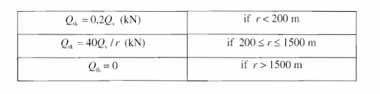
Where:
r is the horizontal radius of the carriageway center line
Qv is the total vertical weight of the maximum concentrated load of the tandem system LM1 i.e.: Σ∝Qi (2Q1k)
Where relevant, lateral forces from skew braking or skidding should be taken into account. A transverse braking force Qtrk equal to 25% (UK NA suggests 50%) of the longitudinal braking or acceleration force Q1k should be considered to act simultaneously with Qtk at the finished carriageway level.
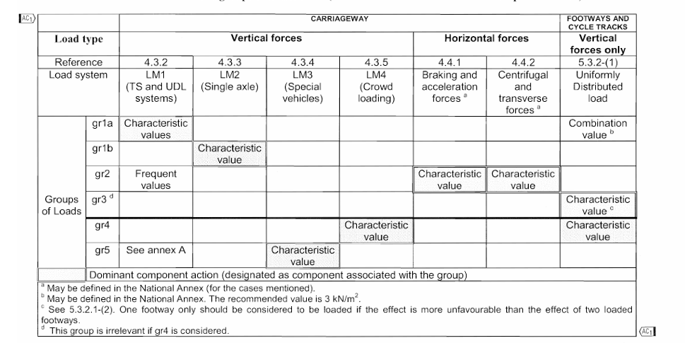
GROUPS OF TRAFFIC LOADS
The group of traffic loads defined in the standards take care of the simultaneity of the loading systems defined as Load Model 1, Load Model 2, Load Model 3, Load Model 4, horizontal forces, and the loads for footways. The simultaneous occurrence of these loads should be considered using Table 4.4a of the standard which are reproduced below. Each of this group of loads are mutually exclusive and should be considered as defining a characteristic action for combination with non-traffic loads.
Table 4.4a of the standard can also be used for defining group of actions representing infrequent action. This is achieved by replacing all characteristic values in Table 4.4 by infrequent values defined in EN 1990, A2, without modifying the other values mentioned in the Table. But the infrequent group gr2 is practically irrelevant for road bridges.
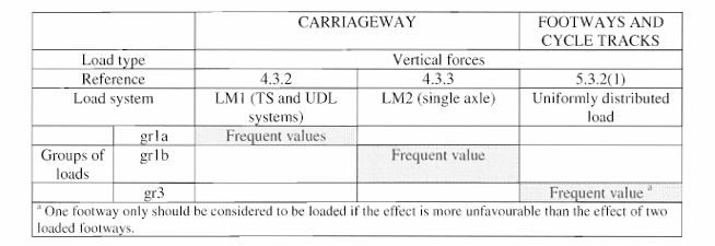
The frequent action can be defined using Table 4.4b of the standard which is reproduced below.
The UK National Annex Approach to Groups of traffic Loads.
According to UK NA, the groups of traffic loads should be taken as defined in Table NA.3 instead of Table 4.4a of BS EN 1991-2.
References
EN 1991-2 (2003) (English): Eurocode 1. Actions on structures. Traffic loads on bridges
BS NA EN 1991-2 (2003) (English): UK National Annex to Eurocode 1. Actions on structures. Traffic loads on bridges