Column design charts are created to simplify the design of reinforced concrete columns. These charts are suitable for columns with symmetrical arrangement of reinforcement and they are produced peculiarly for columns with certain d/h or d’/h ratios.
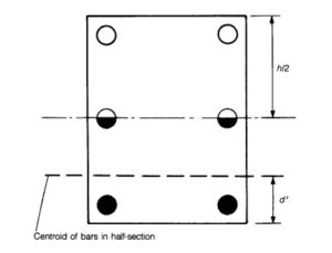
Fundamentally, columns appropriate to be designed using the charts as aides are assumed to have reinforcements concentrated at the corners of such columns, but when they are not a conservative approach should be taken such that d’ becomes the distance from the centroid of bars in half-section of the column as shown in the diagram below.

Although these are very essential charts for the design of symmetrically reinforced column, they however are not particularly present in Eurocode 2. They can only be found in reference materials and manuals such as “How to design concrete structures using Eurocode 2”, “Concise Eurocode” etc.
This article presents a worked example on how to design a column using these charts. The column that shall be designed is column EF which has been previously analyzed here as part of a frame using moment distribution method. The moment in the column has been obtained already and it has been evaluated to be 11.2KNm. We are left with evaluating the axial load on the column.
The axial force of a column in a structural frame may be calculated on the assumption that beams and slabs transmitting force into the particular column are simply supported. By this, the reaction from the column can be calculated which in turn serves as the load on the column. The reaction on the column shall be calculated as follows:
We shall first provide the frame structure below for easy reference.

From basic load distribution technique, column EF supports half of the load acting on both Beam BE and EH. Since the load acting on Beam BE and EH are 207.5 and 117.6 respectively, then the column reaction is:
207.5/2 + 117.6/2 = 162.55KN
Having calculated the axial load on the column, we can now proceed to write down the loads and other design parameters necessary for the column design.
Moment on the column (M) = 11.2KNm
Axial load on the column (N) = 162.55 KN
Length = 4m
b = 300mm
h = 350mm
fck = 25N/mm2
cover = 25mm
Steps in designing the column
-
Check the Slenderness of the column.
The slenderness ratio of the column shall be compared against the limiting slenderness, if the slenderness ratio is greater than the limiting slenderness then the column is declared “slender”. The column is declared “non-slender” if otherwise. This is shown in the below steps.
a. Calculate the effective length of the column
Since the column is braced, the Effective length (lo) is calculated thus:
$
_{\,\,l_0=0.5l\sqrt{\left( \text{1}+\,\,\frac{K_1}{\text{0.45}+\,\,K_1} \right) \left( \text{1}+\,\,\frac{K_2}{\text{0.45}+\,\,K_2} \right)}}
$
K1 and K2 are the relative flexibilities of the top and bottom ends respectively
K1 = $
\frac{\frac{\varSigma I_c}{l}}{\frac{\varSigma 2EI_b}{l}}
$
$
\frac{\frac{\frac{bh^3}{12}}{l}}{2X\frac{\frac{bh^3}{12}}{l}\,\,+\,\,2X\frac{\frac{bh^3}{12}}{l}}
$
$
\frac{\frac{\frac{300 X 350^3}{12}}{4000}}{2X\frac{\frac{300 X 600^3}{12}}{6000}\,\,+\,\,2X\frac{\frac{300 X 600^3}{12}}{6000}}
$
= 267968.75/(1800000 + 1800000)
= 0.074
We do the same thing all over again to get K2
K2 = $
\frac{\frac{\varSigma I_c}{l}}{\frac{\varSigma 2EI_b}{l}}
$
$
\frac{\frac{\frac{bh^3}{12}}{l}}{2X\frac{\frac{bh^3}{12}}{l}\,\,+\,\,2X\frac{\frac{bh^3}{12}}{l}}
$
$
\frac{\frac{\frac{300 X 350^3}{12}}{4000}}{2X\frac{\frac{300 X 600^3}{12}}{6000}\,\,+\,\,2X\frac{\frac{300 X 600^3}{12}}{6000}}
$
= 267968.75/(1800000 + 1800000)
= 0.074
$
_{\,\,l_0=0.5l\sqrt{\left( \text{1}+\,\,\frac{0.074}{\text{0.45}+\,\,0.074} \right) \left( \text{1}+\,\,\frac{0.074}{\text{0.45}+\,\,0.04} \right)}}
$
=2283.8699mm
b. Calculate the radius of gyration
$
r\,\,=\,\,\sqrt{\frac{I}{A}}\,\,=\,\,\sqrt{\frac{\frac{bh^3}{12}}{b\,\,X\,\,h}}\,\,=\,\,\sqrt{\frac{\frac{\text{300}X\,\,350^3}{12}}{\text{300}X\,\,350}}\,\,\,\,=\,\,101.04
$
c. Calculate the slenderness ratio of the column
λ = lo/r = 2283.8699/101.04 = 22.604
d. Calculate the limiting slenderness
λlim = (20 X A X B X C/√n)
A = 0.7, B = 1.1, C = 0.7
(All these assumptions are based on alternative suggestion by the code, check clause 5:8:3:1)
n = NEd /Acfcd = n = 162.55 X 10^3 / (300 X 350 X 0.85 X 25/1.5) = 0.1
λlim = (20 X 0.7 X 1.1 X 0.7/√0.1) = 79.2
Since λlim (79.2) is greater than ⅄ (22.604) then the column is non-slender and second-order moment is not required.
-
Compute the design moment (MED)
The design moment is the greatest of: max (M2, M1) + (Ned) x e
where: M2 and M1 are the top end and bottom end moments of the column.
e is the greater between the eccentricities due to imperfection and minimum required eccentricity of a column.
eccentricity due to imperfection = lo/400 = 2283.8699/400 = 5.7mm
minimum eccentricity required = h/30 ≥ 20mm = 350/30 = 11.7mm
since h/30 < 20, then minimum eccentricity = 20mm
And since minimum eccentricity (20mm) is grater than that due to imperfections (5.7mm) then e is taken as the minimum eccentricity which is 20mm.
M1 = 0, M2 = 11.2KNM. so:
MED= M2 +NED X e
MED = 11.2 + 162.55 X 0.02
= 14.451KNm
-
Use the design Chart to determine the area of reinforcement required
In order to use the design chart, few parameters have to be calculated
-
Determine NED/bhfck
NED/bhfck = 162.55 X 10^3 /300 X 350 X 25 = 0.06
2. Determine MED/bh²fck
MED/bh²fck = 14.451 X 10^6/300 X 350^2 X 25 = 0.02
3. Calculate d’/h
d’/h determines the exact graph that shall be used to determine the reinforcement area.
d’ = c + d/2 = 25 + 16/2 = 33
d’/h = 33/350 = 0.09
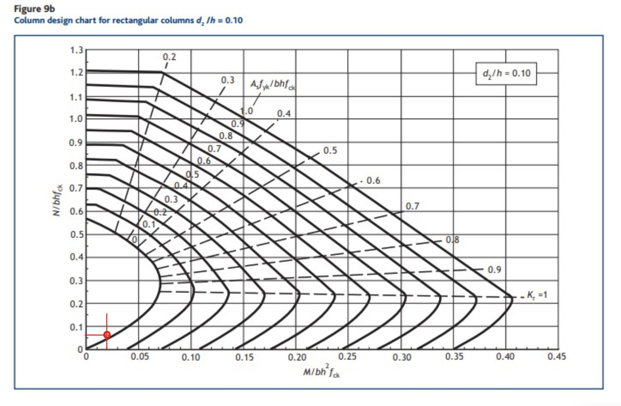
This is approximated to 0.1 and the design chart peculiar to d’/h = 0.1 is used. Fig 9b of “How to design concrete Structures to Eurocode 2” matches this. The chart is reproduced below.
From the design chart, the intersection of MED/bh²fck = 0.02 and N/bhfck = 0.06 falls below the 0 mark. This is shown by the red lines drawn on the chart at the almost bottom left corner.
This implies there is no need to provide reinforcement for the column. However to keep to EC2 directives minimum area of reinforcement shall be provided.
Asmin = 0.1NED/fyd ≥ 0.002Ac = 37.4
0.002Ac = 0.002 X 300 X 350 = 210
Since 0.002Ac (210) > 0.1NED/fyd (37.4), adopt the Area of reinforcement for the column as 210mm²
Hence provide 4Y12 (449.856mm2) as the longitudinal reinforcement of the column
-
Determine the link diameter and spacing
a. Link diameter
The link diameter is the greater of;
- ¼ x maximum diameter of longitudinal bar
- 6mm
¼ x maximum diameter of longitudinal bar = ¼ x 12 = 3mm
Since 3mm > 6mm, hence use 6mm as the link diameter.
b. Link Spacing
The link spacing should be the lesser than;
- 20 x minimum diameter of longitudinal bar
- lesser of the column dimension
- 400mm
20 x minimum diameter of longitudinal bar = 20 x 12 = 240mm
The lesser of the column dimension = 300m
Since 240mm is lesser than 300mm and 400mm, 240mm governs the spacing
Provide 6mm links at 200mm spacing.
It’s awesome designed for me to have a website, which is
good in support of my knowledge. thanks admin
Thank you, I’ve just been looking for information about this subject for ages and yours is the greatest
I have discovered till now. But, what concerning the conclusion? Are you positive about the source?
Hi there! Would you mind if I share your blog with my twitter
group? There’s a lot of people that I think would really enjoy
your content. Please let me know. Thank you
Eine eigene Wallet ist bei diesem Produkt nicht notwendig.
Als Neukunde geben Sie nun Ihre E-Mail-Adresse und
ein starkes Passwort ein. Sie sehen den Bitcoin Kurs etwas weiter unten in diesem
Artikel.
An interesting discussion is worth comment. There’s no doubt that that you should publish more
on this topic, it may not be a taboo subject but typically
people don’t discuss these subjects. To the next!
Best wishes!!
Thanks for sharing your thoughts about daftar slot joker123
deposit pulsa tanpa potongan. Regards
If some one needs to be updated with most recent technologies then he must be go to see this site and
be up to date every day.
Wow that was unusual. I just wrote an extremely long comment but
after I clicked submit my comment didn’t appear.
Grrrr… well I’m not writing all that over again. Anyhow, just wanted
to say superb blog!
Thanks for sharing your thoughts. I really appreciate your efforts and I will be waiting for your next post thank you once
again.
Howdy I am so happy I found your blog, I really found you by error, while I was searching on Bing for something
else, Anyways I am here now and would just like to say thanks a lot for
a marvelous post and a all round exciting blog (I also love the theme/design),
I don’t have time to read through it all at the moment but I have
book-marked it and also added in your RSS feeds,
so when I have time I will be back to read much more, Please
do keep up the awesome b.
Hi! I’ve been reading your site for some time now and finally got the bravery
to go ahead and give you a shout out from Huffman Texas!
Just wanted to mention keep up the excellent job!
Nice blog here! Also your web site loads up very fast! What host are you using?
Can I get your affiliate link to your host? I wish my web site loaded up as fast as
yours lol
What i don’t understood is in truth how you’re no longer really much
more well-liked than you may be right now.
You’re so intelligent. You recognize therefore considerably on the subject of
this subject, made me for my part imagine it from a lot of varied
angles. Its like men and women don’t seem to be involved except it’s something to do with Girl gaga!
Your own stuffs nice. At all times care for it up!
Hi, Neat post. There’s an issue together with your site in web explorer, could check this?
IE nonetheless is the market chief and a good component of
other people will miss your wonderful writing due to this problem.
Hmm it appears like your site ate my first comment
(it was super long) so I guess I’ll just sum it
up what I wrote and say, I’m thoroughly enjoying your blog.
I as well am an aspiring blog writer but I’m still new to everything.
Do you have any recommendations for rookie blog writers?
I’d definitely appreciate it.
I like the helpful information you provide in your articles.
I’ll bookmark your blog and check again here frequently. I’m quite certain I’ll learn a lot
of new stuff right here! Best of luck for the next!
When I initially commented I clicked the “Notify me when new comments are added” checkbox and now
each time a comment is added I get several e-mails with
the same comment. Is there any way you can remove me from that service?
Cheers!
Thanks for every other informative web site. Where
else could I am getting that type of information written in such a perfect manner?
I have a mission that I’m just now operating on, and I have been at
the look out for such information.
I know this site gives quality dependent articles and extra information, is there any other site which offers such data in quality?
Hey! Do you know if they make any plugins to protect against
hackers? I’m kinda paranoid about losing everything I’ve worked
hard on. Any suggestions?
I got this website from my friend who told me about this web site and now this time I am visiting this web page and reading very informative articles or reviews here.
Hey there! Someone in my Facebook group shared this website with us so I came
to check it out. I’m definitely enjoying the
information. I’m book-marking and will be tweeting this
to my followers! Wonderful blog and fantastic
style and design.
This is my first time visit at here and i am truly impressed to read everthing
at one place.
I am now not certain where you’re getting your information,
but good topic. I needs to spend some time finding out more or figuring out
more. Thank you for magnificent information I was looking for this information for my mission.
May I just say what a relief to find somebody that genuinely knows what they’re talking about
on the internet. You definitely know how to
bring a problem to light and make it important.
More people need to read this and understand this side
of the story. I can’t believe you are not more popular given that you surely have the gift.
Somebody necessarily help to make seriously articles I would state.
This is the first time I frequented your web page and thus far?
I surprised with the analysis you made to make this particular publish extraordinary.
Great task!
What’s up, yup this paragraph is truly fastidious and
I have learned lot of things from it regarding blogging.
thanks.
Hi to every single one, it’s in fact a nice for me to pay a quick visit this site, it consists of useful Information.
It’s going to be finish of mine day, except before ending I am reading this fantastic piece of writing
to improve my know-how.
Hi it’s me, I am also visiting this site daily, this site is in fact good and the
viewers are in fact sharing pleasant thoughts.
Very good blog you have here but I was curious about if you knew of any discussion boards that cover the
same topics talked about in this article? I’d really
like to be a part of online community where I can get advice from other knowledgeable
individuals that share the same interest. If
you have any suggestions, please let me know. Bless you!
Greate article. Keep writing such kind of info on your site.
Im really impressed by your blog.
Hey there, You have done an incredible job. I will certainly digg
it and in my view suggest to my friends.
I’m confident they’ll be benefited from this site.
Hello Dear, are you really visiting this web
site regularly, if so after that you will without doubt take nice experience.
Normally I do not learn article on blogs, but I would like
to say that this write-up very pressured me to check out and do so!
Your writing taste has been surprised me. Thank you, very
great post.
Thanks for finally writing about > Design of Column to Eurocode 2
using Design Chart – worked example – First Principle Engineering
< Loved it!
Hello, i think that i saw you visited my website thus i came to “return the favor”.I am trying to find things to improve my website!I suppose its ok to
use some of your ideas!!
Hello There. I found your blog using msn. This is a really well written article.
I will make sure to bookmark it and come back to read more of your
useful information. Thanks for the post. I’ll definitely return.
I have read so many articles or reviews about the
blogger lovers but this paragraph is truly a fastidious piece of
writing, keep it up.
What’s up, I would like to subscribe for this blog to
get newest updates, therefore where can i do it please help out.
Hi i am kavin, its my first time to commenting anyplace, when i
read this paragraph i thought i could also make comment due to this sensible paragraph.
Greetings! This is my 1st comment here so I just wanted to give a quick shout out and tell you I genuinely enjoy reading your articles.
Can you recommend any other blogs/websites/forums that deal with
the same subjects? Thanks a ton!
If you wish for to improve your experience just keep visiting this website
and be updated with the most up-to-date news posted here.
Hello, i think that i saw you visited my weblog so i came to “return the favor”.I am trying to find things to improve my site!I suppose
its ok to use a few of your ideas!!
Thanks on your marvelous posting! I truly enjoyed reading
it, you may be a great author. I will always bookmark your blog and will come back from now on. I want to encourage you to
ultimately continue your great job, have a nice morning!
As the admin of this web page is working, no hesitation very rapidly it will be famous, due to its feature contents.
Hello, this weekend is pleasant in favor of me, since this occasion i am
reading this enormous educational article here at my residence.
Hiya! I know this is kinda off topic however I’d figured I’d ask.
Would you be interested in trading links or maybe guest authoring a
blog article or vice-versa? My website covers a lot of the same subjects as yours and I believe we could greatly
benefit from each other. If you’re interested feel free to shoot me an email.
I look forward to hearing from you! Superb blog by the way!
Saved as a favorite, I love your web site!
Hey there! I’ve been following your blog for a while now and
finally got the courage to go ahead and give you a shout
out from Humble Texas! Just wanted to tell you keep
up the good job!
What’s Going down i am new to this, I stumbled upon this
I’ve found It absolutely useful and it has aided me out loads.
I hope to contribute & aid different customers like its helped
me. Great job.
These are actually fantastic ideas in about blogging.
You have touched some pleasant things here. Any way
keep up wrinting.
Remarkable issues here. I’m very satisfied to see your article.
Thanks a lot and I am having a look ahead to touch you.
Will you kindly drop me a mail?
Hi there! I could have sworn I’ve been to this website before but after browsing through some of the
articles I realized it’s new to me. Nonetheless, I’m definitely happy I came across it and I’ll be book-marking it and checking back regularly!
We are a group of volunteers and starting a new scheme in our community.
Your website provided us with valuable information to work on. You’ve
done a formidable job and our entire community will be thankful to you.
I have to thank you for the efforts you have put in writing this site.
I am hoping to view the same high-grade content by you in the future as well.
In truth, your creative writing abilities has motivated me to
get my own blog now 😉
Appreciation to my father who shared with me about this blog, this web
site is in fact amazing.
Everything is very open with a very clear clarification of the issues.
It was definitely informative. Your website is very useful.
Many thanks for sharing!
Awesome article.
It has a great deal of functions that can aid you to obtain your web site rated on the first page of Google.
We are a group of volunteers and opening a new scheme in our community.
Your web site provided us with valuable info to work on.
You’ve done a formidable job and our whole community will be
grateful to you.
This is my first time pay a quick visit at here and i am truly
impressed to read everthing at alone place.
It’s very simple to find out any topic on net as compared to textbooks,
as I found this article at this website.
I am really grateful to the holder of this web page who has shared this
wonderful paragraph at at this time.
Hello! I know this is kinda off topic but I’d figured I’d ask.
Would you be interested in exchanging links or maybe guest writing a blog
article or vice-versa? My website discusses a lot of the same subjects as yours and I believe we could greatly benefit from each other.
If you’re interested feel free to send me an e-mail. I look forward to hearing from you!
Superb blog by the way!
I think this is among the most significant information for me.
And i’m glad reading your article. But should remark
on few general things, The website style
is great, the articles is really great : D. Good job,
cheers
Unquestionably believe that which you stated. Your favorite justification seemed to be on the net the easiest thing to be aware of.
I say to you, I definitely get irked while people think
about worries that they plainly don’t know about.
You managed to hit the nail upon the top as well as defined out the whole thing without having side-effects ,
people can take a signal. Will likely be back to get more.
Thanks
Good way of telling, and good post to take facts about my presentation topic, which i
am going to deliver in college.
fantastic post, very informative. I wonder why the opposite
specialists of this sector don’t notice this. You must
proceed your writing. I’m confident, you have a great readers’ base already!
Hi, I desire to subscribe for this web site
to obtain hottest updates, therefore where can i do it please help out.
First off I would like to say great blog! I had a quick question that I’d
like to ask if you don’t mind. I was curious to find out how you center yourself and clear your
head prior to writing. I’ve had a hard time clearing my mind in getting my ideas out there.
I do take pleasure in writing however it just seems like
the first 10 to 15 minutes are generally wasted simply just trying to figure
out how to begin. Any suggestions or hints? Kudos!
Thanks for finally writing about > Design of Column to
Eurocode 2 using Design Chart – worked example – First
Principle Engineering < Loved it!
It’s truly a nice and useful piece of information. I’m glad that you just shared this useful information with us.
Please stay us informed like this. Thanks for sharing.
Hey I know this is off topic but I was wondering if you knew of any widgets I could add
to my blog that automatically tweet my newest twitter updates.
I’ve been looking for a plug-in like this for quite some time and was hoping maybe
you would have some experience with something like this.
Please let me know if you run into anything. I truly enjoy reading your
blog and I look forward to your new updates.
Nice post. I was checking constantly this blog and I’m impressed!
Very helpful info specifically the last part 🙂 I care for such information much.
I was seeking this certain information for a long time.
Thank you and good luck.
Hey! This is my first visit to your blog! We are a team of volunteers
and starting a new initiative in a community in the same niche.
Your blog provided us beneficial information to work on. You have done a outstanding job!
It is appropriate time to make a few plans for the long run and it is time to be happy.
I have read this post and if I may I want to counsel you some interesting issues or tips.
Perhaps you can write next articles regarding this article.
I desire to read even more things approximately it!
Good day I am so excited I found your weblog, I really found you by accident, while I was searching on Yahoo for something else, Regardless I am here now and would just
like to say thank you for a fantastic post and a
all round thrilling blog (I also love the theme/design), I don’t have time to
read it all at the moment but I have book-marked it and also included your RSS feeds, so when I have time I will be back to read
much more, Please do keep up the fantastic work.
Thank you a bunch for sharing this with all of us you really understand what you are speaking
about! Bookmarked. Kindly also seek advice from my site =).
We may have a link change contract between us
Hey! This is my first visit to your blog! We are a group of volunteers and starting
a new project in a community in the same niche. Your blog provided us useful information to work on. You have done a
marvellous job!
Normally I don’t read article on blogs, but I would like to say that this write-up
very pressured me to try and do so! Your writing taste has been surprised
me. Thanks, very nice post.
Но они интересны вначале, пока не разобрался, что делать.
В наши дни многие казино могут приветствовать вас бонусом или подарком.
I’m now not sure the place you’re getting your info, however great topic.
I needs to spend some time studying much more or figuring out more.
Thank you for excellent information I used to
be in search of this info for my mission.
Incredible a lot of superb facts.
Amazing! Its genuinely awesome paragraph, I have got much clear idea on the topic of from this article.
You actually explained that effectively!
Inspiring story there. What occurred after? Thanks!
Nice post. I was checking continuously this blog and I am impressed!
Extremely helpful information specifically the last
part 🙂 I care for such info much. I was looking for this certain info for a long time.
Thank you and best of luck.
It’s remarkable to go to see this web site and reading the views of all mates about this
post, while I am also eager of getting knowledge.
This site was… how do I say it? Relevant!! Finally I’ve found something that helped me.
Thanks a lot!
Thanks in support of sharing such a good thought, article
is pleasant, thats why i have read it completely
You said it adequately.!
Wonderful information Regards.
Lovely facts. With thanks!
Peculiar article, totally what I wanted to find.
Hola! I’ve been following your site for a while now and finally got the courage to go ahead and give you a shout out from Dallas Texas!
Just wanted to say keep up the fantastic work!
Info clearly utilized..
Hi, Neat post. There’s an issue with your web site in web
explorer, might test this? IE still is the marketplace leader and a
large portion of people will miss your magnificent writing because of this problem.
If some one wants expert view regarding blogging after that i advise him/her to pay a quick visit this blog, Keep up the pleasant job.
Thanks a lot, A good amount of postings!
Appreciate it! Loads of data.
You mentioned this well.
Regards, Very good stuff!
You said it very well.!
You reported that perfectly!
You made your stand very effectively.!
Your style is unique compared to other folks I have read stuff
from. Thanks for posting when you’ve got the opportunity,
Guess I’ll just book mark this blog.
Thanks for finally writing about > Design of Column to Eurocode 2 using Design Chart – worked example
– First Principle Engineering < Loved it!
You could certainly see your expertise in the
article you write. The world hopes for even more passionate writers like you who are not afraid to say how they believe.
Always follow your heart.
Thankfulness to my father who stated to me concerning this web site, this blog is actually awesome.
Hey I know this is off topic but I was wondering if you knew of any widgets I could add to my blog that automatically tweet my newest twitter
updates. I’ve been looking for a plug-in like this for quite
some time and was hoping maybe you would have some experience with something like this.
Please let me know if you run into anything. I truly enjoy reading your blog and I look forward to your new updates.
Thank you for some other informative site. Where else may I am getting that
kind of information written in such an ideal approach?
I have a mission that I am simply now operating on, and I have been on the glance out for such info.
Good post. I learn something totally new and
challenging on blogs I stumbleupon on a daily basis. It will always be helpful to read through content from other authors and
use something from other sites.
You actually mentioned this fantastically!
Appreciate it, Quite a lot of write ups!
What’s up colleagues, its great article concerning cultureand entirely defined, keep it up all the time.
Hi this is kind of of off topic but I was wondering if blogs use WYSIWYG editors or if you have to manually code with HTML.
I’m starting a blog soon but have no coding expertise so I wanted to get
guidance from someone with experience. Any help would be greatly appreciated!
Nicely put. With thanks.
Hi, just wanted to say, I enjoyed this article. It was practical.
Keep on posting!
If you would like to take a great deal from this piece of writing then you have
to apply these methods to your won web site.
Hello there I am so glad I found your webpage, I really found you by error, while I was researching on Yahoo
for something else, Anyhow I am here now and would just like to say many thanks for a marvelous post and a all round entertaining blog (I also love
the theme/design), I don’t have time to look over it all at the
moment but I have book-marked it and also included your RSS feeds,
so when I have time I will be back to read much more, Please do keep
up the great work.
I just like the helpful info you provide in your articles.
I’ll bookmark your weblog and check again here regularly. I’m slightly certain I’ll
be told many new stuff proper here! Good luck for the next!
I every time used to read article in news papers but now as I am a user
of net thus from now I am using net for articles or reviews, thanks to web.
Appreciating the time and effort you put into your blog and detailed information you offer.
It’s great to come across a blog every once in a
while that isn’t the same unwanted rehashed information. Wonderful read!
I’ve saved your site and I’m including your RSS feeds to my Google account.
Whoa a good deal of very good information!
Hello to all, because I am truly eager of reading this website’s post to be updated regularly.
It includes fastidious stuff.
Hello would you mind letting me know which web host you’re
using? I’ve loaded your blog in 3 completely different browsers
and I must say this blog loads a lot faster then most.
Can you suggest a good hosting provider at a reasonable price?
Kudos, I appreciate it!
continuously i used to read smaller posts that also clear their motive, and that is also happening
with this paragraph which I am reading now.
Wow, wonderful blog layout! How long have you been blogging for?
you made blogging look easy. The overall look of your site is magnificent,
as well as the content!
Seriously loads of awesome material.
Many thanks, I enjoy this.
Really many of wonderful facts.
These are genuinely impressive ideas in regarding blogging.
You have touched some fastidious points here.
Any way keep up wrinting.
First of all I want to say superb blog! I had a quick question in which I’d like to ask if you do
not mind. I was interested to find out how you center yourself and clear
your head before writing. I have had a difficult time clearing my mind
in getting my thoughts out. I truly do take pleasure in writing but it just seems like
the first 10 to 15 minutes tend to be lost just trying to figure out how to begin.
Any suggestions or tips? Appreciate it!
I was curious if you ever thought of changing the page layout of your site?
Its very well written; I love what youve got to say. But maybe you could a little more in the way of content so people could
connect with it better. Youve got an awful lot of text for only having one or 2 images.
Maybe you could space it out better?
FVOoKWTgQapmAH
yIwqElak
Hey there! I know this is kinda off topic but I’d figured I’d ask.
Would you be interested in exchanging links or maybe
guest authoring a blog article or vice-versa?
My site goes over a lot of the same topics as yours and I believe
we could greatly benefit from each other. If you happen to be interested feel free to send me an e-mail.
I look forward to hearing from you! Fantastic blog by the way!
You have made the point.
Awesome advice, Regards!
You revealed that wonderfully.
You said it very well.!
Reliable info Many thanks.
Cheers, I value this.
You actually explained that very well.
Really lots of very good knowledge!
Appreciate it! A good amount of advice.
Nicely put. With thanks!
Position nicely used!.
Regards, A good amount of write ups.
Watch movies from the guy’s perspective to feel like you’re right in the center of the action and get a good view! You can get big booties in virtually any other category it is possible to think of! Whether you’re into curvy teenagers, attractive MILFs, or thick Asians, they all have an area here. Check out the bouncing, backshots, and incredible action in group sex, gangbangs, anal, one-on-one, and much more.
Kudos! I enjoy this.
Really a lot of beneficial tips.
Thanks for your tips about this blog. 1 thing I would want to say is that purchasing gadgets items over the Internet is certainly not new. The fact is, in the past decade alone, the marketplace for online gadgets has grown substantially. Today, you can find practically virtually any electronic gizmo and gizmo on the Internet, from cameras plus camcorders to computer elements and video gaming consoles.
I am curious to find out what blog platform you are working with? I’m having some minor security problems with my latest blog and I’d like to find something more risk-free. Do you have any recommendations?
Really a lot of wonderful material.
Amazing many of beneficial information.
Thank you. Numerous information!
fantastic issues altogether, you simply gained a new reader. What might you recommend about your submit that you just made a few days in the past? Any certain?
You explained this really well.
Very good facts Thanks!
This is nicely said! .
I have seen that charges for internet degree gurus tend to be an excellent value. Like a full Bachelor’s Degree in Communication in the University of Phoenix Online consists of Sixty credits with $515/credit or $30,900. Also American Intercontinental University Online gives a Bachelors of Business Administration with a whole education course element of 180 units and a tuition fee of $30,560. Online studying has made getting the education far less difficult because you can certainly earn your own degree from the comfort in your home and when you finish from work. Thanks for all the tips I have learned through your blog.
Hello! I simply would like to give you a large thumbs up with the great information you could have here on this post I’ll be returning to your site to get more detailed soon
When I originally commented I clicked the “Notify me when new comments are added” checkbox and now each time a comment is added I getthree emails with the same comment Is there any way you can remove me from that service?Thanks!
Howdy would you mind letting me know which webhost you’re using? I’ve loaded your blog in 3 different browsers and I must say this blog loads a lot faster then most. Can you recommend a good hosting provider at a honest price? Kudos, I appreciate it!
You said it adequately.!
Excellent post. I certainly appreciate this website.
Stick with it!
Awesome post! I liked the details on HGH and its impact on muscle building.
It fits perfectly with my fitness exercise routine. Thanks for sharing!|Loved this article about HGH and muscle building.
It’s very helpful for my fitness exercise routine.
Thanks!
I have been browsing online more than 4 hours today, yet I never found any interesting article like yours.
It’s pretty worth enough for me. In my view, if all
website owners and bloggers made good content
as you did, the net will be a lot more useful than ever before.|
I could not resist commenting. Well written!|
I’ll immediately snatch your rss feed as I can’t find your
e-mail subscription hyperlink or e-newsletter service.
Do you have any? Kindly permit me recognize so that I could subscribe.
Thanks.|
It’s appropriate time to make some plans for the future and it
is time to be happy. I have read this post and
if I could I wish to suggest you some interesting things or advice.
Maybe you can write next articles referring to
this article. I desire to read even more things about it!|
It is the best time to make some plans for the future and it is time to be happy.
I have learn this submit and if I may I want to
counsel you some interesting things or suggestions. Perhaps you can write next articles referring to this article.
I wish to learn even more issues about it!|
I’ve been surfing on-line more than 3 hours nowadays, but I by no means
found any interesting article like yours. It is beautiful price sufficient for me.
Personally, if all website owners and bloggers made
just right content as you probably did, the internet will likely be a lot more useful than ever before.|
Ahaa, its pleasant dialogue on the topic of this paragraph here at this website,
I have read all that, so now me also commenting here.|
I am sure this post has touched all the internet viewers,
its really really pleasant paragraph on building up new web site.|
Wow, this piece of writing is nice, my sister is analyzing such things, so I am going to convey her.|
bookmarked!!, I love your web site!|
Way cool! Some extremely valid points! I appreciate
you penning this post and the rest of the site is very good.|
Hi, I do think this is an excellent site. I stumbledupon it 😉 I
will return yet again since i have book marked it. Money and freedom is
the greatest way to change, may you be rich and continue to guide other people.|
Woah! I’m really loving the template/theme of this blog.
It’s simple, yet effective. A lot of times it’s hard to get that “perfect balance” between user friendliness and visual
appeal. I must say you have done a amazing job with this.
In addition, the blog loads super quick for me on Chrome.
Excellent Blog!|
These are truly impressive ideas in concerning blogging.
You have touched some nice points here. Any way keep up wrinting.|
I love what you guys tend to be up too. This sort of clever work and reporting!
Keep up the amazing works guys I’ve included you guys to blogroll.|
Hey! Someone in my Facebook group shared this site
with us so I came to give it a look. I’m definitely enjoying the information. I’m
bookmarking and will be tweeting this to my followers! Excellent
blog and amazing design.|
I really like what you guys are up too. This sort of clever work and
reporting! Keep up the terrific works guys I’ve added you guys to my personal blogroll.|
Hey would you mind stating which blog platform you’re using?
I’m going to start my own blog soon but I’m having a tough time selecting between BlogEngine/Wordpress/B2evolution and Drupal.
The reason I ask is because your layout seems different then most blogs and I’m looking for something
unique. P.S My apologies for being off-topic but I had
to ask!|
Howdy would you mind letting me know which web host you’re utilizing?
I’ve loaded your blog in 3 different internet browsers and I must
say this blog loads a lot faster then most. Can you recommend a good
web hosting provider at a honest price? Thanks, I appreciate it!|
I love it when folks come together and share opinions.
Great blog, stick with it!|
Thank you for the good writeup. It in fact was a amusement account it.
Look advanced to more added agreeable from you! However, how can we communicate?|
Hey just wanted to give you a quick heads up. The text in your article seem to be running off
the screen in Safari. I’m not sure if this is a formatting
issue or something to do with web browser compatibility but I figured I’d
post to let you know. The design look great though!
Hope you get the issue solved soon. Cheers|
This is a topic that’s near to my heart… Best wishes!
Where are your contact details though?|
It’s very trouble-free to find out any matter on net as compared to books, as I found this piece
of writing at this web page.|
Does your website have a contact page? I’m having problems locating it
but, I’d like to shoot you an email. I’ve got some recommendations for your blog you might
be interested in hearing. Either way, great blog and I look forward to seeing it
improve over time.|
Hello! I’ve been reading your web site for a while now and finally
got the bravery to go ahead and give you a shout out from Huffman Tx!
Just wanted to mention keep up the fantastic job!|
Greetings from Ohio! I’m bored at work so I decided to check out your website on my
iphone during lunch break. I really like the info you present
here and can’t wait to take a look when I get home. I’m surprised
at how quick your blog loaded on my cell phone .. I’m not even using
WIFI, just 3G .. Anyhow, great site!|
Its such as you read my thoughts! You appear to know so much
approximately this, such as you wrote the book in it or something.
I feel that you could do with some p.c. to drive the message house a bit, however other than that,
this is magnificent blog. A fantastic read.
I will definitely be back.|
I visited several blogs but the audio feature for audio songs present at
this web site is genuinely marvelous.|
Howdy, i read your blog occasionally and i own a similar one and i was just wondering if you get a lot of
spam responses? If so how do you protect against it, any plugin or anything you
can recommend? I get so much lately it’s driving me insane so any help is very much appreciated.|
Greetings! Very helpful advice in this particular article!
It is the little changes which will make the largest changes.
Thanks for sharing!|
I absolutely love your blog.. Excellent colors & theme.
Did you build this amazing site yourself? Please reply back as I’m looking to create my very own website and
would love to know where you got this from
or exactly what the theme is named. Many thanks!|
Hi there! This blog post couldn’t be written any better!
Looking through this article reminds me of my previous roommate!
He constantly kept talking about this. I’ll forward this information to him.
Fairly certain he’ll have a great read. Many thanks for sharing!|
Wow! This blog looks just like my old one! It’s on a entirely different topic but it has pretty much the same page layout and design. Superb choice of colors!|
There’s definately a lot to learn about this topic. I like all
the points you’ve made.|
You’ve made some decent points there. I looked on the internet to find out more about the issue and found most individuals will go along
with your views on this web site.|
Hello, I check your blogs daily. Your writing style is witty, keep it up!|
I simply couldn’t leave your web site prior to suggesting that I actually enjoyed the usual information a person provide
to your visitors? Is gonna be back frequently to inspect new posts|
I needed to thank you for this wonderful read!! I certainly loved every little bit of it.
I’ve got you bookmarked to look at new things you post…|
Hello, just wanted to mention, I enjoyed this article.
It was practical. Keep on posting!|
Hello, I enjoy reading all of your post. I wanted to write a
little comment to support you.|
I constantly spent my half an hour to read this webpage’s
articles all the time along with a cup of coffee.|
I for all time emailed this web site post page to all my friends,
for the reason that if like to read it then my
contacts will too.|
My coder is trying to persuade me to move to .net from PHP.
I have always disliked the idea because of the costs.
But he’s tryiong none the less. I’ve been using Movable-type on a
number of websites for about a year and am worried about switching to another
platform. I have heard very good things about blogengine.net.
Is there a way I can transfer all my wordpress posts into it?
Any kind of help would be greatly appreciated!|
Good day! I could have sworn I’ve visited your blog before but after going through some of
the articles I realized it’s new to me. Nonetheless, I’m definitely pleased I stumbled upon it and I’ll
be book-marking it and checking back frequently!|
Wonderful article! This is the type of information that are
meant to be shared around the internet. Shame on Google for now not positioning this
submit higher! Come on over and consult with my site .
Thanks =)|
Heya i am for the first time here. I came across this board and I find It
truly useful & it helped me out a lot. I hope to give something back
and aid others like you helped me.|
Howdy, I do think your blog may be having web browser compatibility problems.
Whenever I take a look at your site in Safari, it looks fine
however, if opening in IE, it has some overlapping issues.
I just wanted to give you a quick heads up! Besides that, wonderful blog!|
Someone essentially assist to make seriously articles I’d state.
That is the first time I frequented your web page and to this point?
I surprised with the analysis you made to create this particular publish incredible.
Fantastic process!|
Heya i am for the primary time here. I found this board and I to find
It truly helpful & it helped me out much. I’m hoping to provide one thing
again and aid others like you helped me.|
Hey there! I simply want to give you a big thumbs up for your great info you have
here on this post. I’ll be coming back to your website for more soon.|
I all the time used to study piece of writing in news papers but now as I am a user of web so from now I am using net
for posts, thanks to web.|
Your way of telling all in this piece of writing is actually pleasant, all be capable of simply understand it,
Thanks a lot.|
Hello there, I found your site via Google at the same time
as searching for a comparable matter, your web site came up, it appears to be like great.
I’ve bookmarked it in my google bookmarks.
Hi there, just was alert to your blog through Google, and located that it is truly informative.
I’m gonna watch out for brussels. I’ll appreciate when you continue this in future.
Many other folks will be benefited out of your writing. Cheers!|
I am curious to find out what blog platform you are using?
I’m having some minor security issues with my latest website and I’d like to find something
more risk-free. Do you have any solutions?|
I am extremely impressed with your writing skills and also with the layout on your blog.
Is this a paid theme or did you modify it yourself?
Either way keep up the nice quality writing, it’s rare to see a great blog
like this one nowadays.|
I am really inspired with your writing talents and also with the structure
in your blog. Is this a paid theme or did you modify it your self?
Either way stay up the excellent high quality writing,
it is rare to peer a great weblog like this one these days..|
Hi, Neat post. There’s an issue together with your website in internet explorer, might test this?
IE still is the market leader and a good section of other folks will omit your
wonderful writing due to this problem.|
I am not sure where you’re getting your info, but good topic.
I needs to spend some time learning more or understanding more.
Thanks for fantastic information I was looking for this information for my mission.|
Hello, i think that i saw you visited my weblog so i came to “return the
favor”.I’m trying to find things to enhance my website!I suppose its ok to use some of your ideas!!|
Hello, i think that i noticed you visited my website thus i
came to return the prefer?.I’m attempting to to find things to improve my website!I guess its adequate to use a few of your concepts!!|
Hello there, just became alert to your blog through Google, and
found that it is truly informative. I’m going to watch out for
brussels. I’ll appreciate if you continue this in future. A lot of people will be benefited
from your writing. Cheers!|
I’m no longer certain where you are getting your information, but great topic.
I needs to spend some time studying more or working out more.
Thanks for magnificent info I used to be looking for
this info for my mission.|
Hi my loved one! I wish to say that this article is amazing,
great written and include approximately all important infos.
I would like to peer more posts like this .|
hello!,I love your writing so much! share we communicate extra about your article on AOL?
I require an expert on this space to resolve
my problem. May be that’s you! Having a look ahead to see you.
|
I am really loving the theme/design of your weblog. Do you ever run into any browser compatibility issues?
A few of my blog visitors have complained about my website not operating correctly in Explorer but
looks great in Safari. Do you have any solutions to help fix this problem?|
Great information. Lucky me I found your blog by accident (stumbleupon).
I’ve book marked it for later!|
It’s great that you are getting thoughts from
this piece of writing as well as from our argument made here.|
If you desire to grow your experience only keep visiting
this web page and be updated with the most recent news update posted here.|
What’s Happening i am new to this, I stumbled upon this I have discovered It positively helpful and it has helped me out loads.
I hope to give a contribution & assist different customers
like its helped me. Good job.|
Hurrah, that’s what I was looking for, what a stuff!
existing here at this blog, thanks admin of this site.|
If you want to take much from this article then you have to
apply these strategies to your won weblog.|
It’s an remarkable article designed for all the online visitors;
they will obtain advantage from it I am sure.|
I’ve read several excellent stuff here. Certainly value bookmarking for revisiting.
I wonder how much attempt you put to create such a excellent informative website.|
That is a really good tip especially to those new to the blogosphere.
Simple but very precise info… Thanks for sharing this one.
A must read article!|
I have been exploring for a little bit for any high quality articles
or blog posts in this sort of space . Exploring in Yahoo I finally stumbled upon this site.
Reading this information So i’m glad to convey that I have an incredibly good uncanny feeling I came upon exactly what
I needed. I such a lot no doubt will make sure to don?t omit this site and give it a look regularly.|
Having read this I thought it was rather enlightening.
I appreciate you finding the time and energy to put
this information together. I once again find myself personally spending way too much time both reading and
leaving comments. But so what, it was still worthwhile!|
Quality articles or reviews is the main to interest the users to visit the web site,
that’s what this website is providing.|
Link exchange is nothing else however it is simply placing the other person’s blog link on your page at suitable place and
other person will also do same in favor of you.|
I have read so many content regarding the blogger lovers but this paragraph is
truly a fastidious piece of writing, keep it up.|
Truly no matter if someone doesn’t know afterward its up to other users that
they will assist, so here it occurs.|
You could certainly see your skills within the work you write.
The arena hopes for more passionate writers like you who are not afraid to say how they
believe. Always go after your heart.|
Great article. I’m going through a few of these
issues as well..|
Great site you have got here.. It’s difficult to find quality writing
like yours nowadays. I seriously appreciate individuals like you!
Take care!!|
I was suggested this web site by my cousin. I’m not sure
whether this post is written by him as nobody else know such detailed
about my problem. You’re wonderful! Thanks!|
Very good article! We will be linking to this great article on our
site. Keep up the great writing.|
Oh my goodness! Incredible article dude! Thanks, However I am encountering
issues with your RSS. I don’t understand why I can’t join it.
Is there anyone else having identical RSS problems? Anybody who knows the answer will you kindly respond?
Thanks!!|
Great blog! Do you have any hints for aspiring writers?
I’m planning to start my own website soon but I’m a little lost on everything.
Would you propose starting with a free platform like WordPress
or go for a paid option? There are so many options out there that I’m totally overwhelmed ..
Any tips? Thanks a lot!|
It’s difficult to find knowledgeable people about this topic, however,
you sound like you know what you’re talking about! Thanks|
I don’t even understand how I ended up here, however I assumed this submit used to
be good. I don’t realize who you’re however definitely you are going to a well-known blogger
if you happen to aren’t already. Cheers!|
Fastidious response in return of this issue with real arguments and describing
the whole thing regarding that.|
I do not even know how I ended up here, but I thought this post was great.
I don’t know who you are but certainly you are going to a famous blogger if
you are not already 😉 Cheers!|
We are a bunch of volunteers and starting a new scheme
in our community. Your web site offered us with helpful information to work on. You have performed an impressive job and our whole community will likely be
grateful to you.|
Fine way of explaining, and nice piece of writing to take facts concerning my presentation topic, which i am going to present
in academy.|
Great blog right here! Additionally your website so much up
very fast! What web host are you the use of? Can I am getting your affiliate link on your host?
I wish my website loaded up as fast as yours lol|
I love your blog.. very nice colors & theme.
Did you make this website yourself or did you hire
someone to do it for you? Plz respond as I’m looking to design my own blog and would
like to find out where u got this from. many thanks|
We’re a group of volunteers and opening a new
scheme in our community. Your website provided us with valuable information to work on. You have done a formidable job and our entire community will be thankful to you.|
Appreciate this post. Will try it out.|
Asking questions are truly pleasant thing if you are not understanding anything completely, however
this post provides pleasant understanding yet.|
Have you ever considered about adding a little bit more than just your articles?
I mean, what you say is valuable and all. Nevertheless imagine if you added some great visuals or video clips to give your posts more,
“pop”! Your content is excellent but with pics
and videos, this website could definitely be one of the greatest in its niche.
Superb blog!|
Your style is unique compared to other people I have read stuff from.
Many thanks for posting when you have the opportunity, Guess
I will just book mark this blog.|
Pretty nice post. I just stumbled upon your blog and wanted to say that I’ve really loved surfing around your weblog posts.
After all I will be subscribing for your feed and I’m hoping you write once more soon!|
I’m amazed, I have to admit. Rarely do I come across a blog that’s both educative and interesting, and without
a doubt, you’ve hit the nail on the head.
The issue is an issue that not enough people
are speaking intelligently about. Now i’m very happy I stumbled across this in my hunt
for something relating to this.|
Hmm it appears like your website ate my first
comment (it was super long) so I guess I’ll just sum it up what I had written and say, I’m thoroughly enjoying your blog.
I as well am an aspiring blog writer but I’m still new to the whole thing.
Do you have any points for inexperienced blog writers?
I’d definitely appreciate it.|
Pretty nice post. I just stumbled upon your weblog and
wanted to say that I have truly enjoyed surfing around your blog posts.
In any case I’ll be subscribing to your rss feed and I hope you write again very soon!|
I like the valuable information you provide in your articles.
I’ll bookmark your blog and check again here regularly.
I am quite sure I’ll learn lots of new stuff
right here! Good luck for the next!|
If you are going for best contents like myself, simply pay
a visit this website daily for the reason that it gives quality contents,
thanks|
Write more, thats all I have to say. Literally, it seems as though you
relied on the video to make your point. You definitely know what
youre talking about, why waste your intelligence on just posting videos to your weblog when you could
be giving us something informative to read?|
Very descriptive blog, I enjoyed that bit. Will there be a part 2?|
Nice post. I used to be checking constantly this weblog
and I’m impressed! Extremely helpful info specially the final
phase 🙂 I care for such information much. I was looking for this certain information for a long
time. Thank you and good luck. |
Great post. I was checking constantly this blog and I’m impressed!
Very useful information particularly the last part 🙂 I care for such info a lot.
I was seeking this certain info for a very long time. Thank you and best of luck.|
Awesome post.|
After checking out a few of the blog articles on your blog, I honestly appreciate your technique of
blogging. I bookmarked it to my bookmark webpage list and will be checking back soon. Please check out my website as
well and let me know what you think.|
An interesting discussion is worth comment. I
do think that you should publish more about this subject,
it might not be a taboo subject but typically folks don’t talk about these issues.
To the next! Kind regards!!|
naturally like your website but you need to test the
spelling on several of your posts. A number of them are
rife with spelling problems and I in finding it very
troublesome to inform the truth nevertheless I’ll certainly
come again again.|
I do believe all of the ideas you’ve presented for your post.
They are very convincing and will certainly work. Still, the posts are too short for novices.
May just you please lengthen them a little from
subsequent time? Thanks for the post.|
We stumbled over here by a different page and thought I might
check things out. I like what I see so now i am following
you. Look forward to looking into your web page for a second time.|
Very nice write-up. I definitely appreciate this website.
Continue the good work!|
Have you ever considered publishing an ebook or guest authoring on other sites?
I have a blog based upon on the same information you discuss and would love to have you share
some stories/information. I know my readers would enjoy your work.
If you’re even remotely interested, feel free to shoot me an email.|
My spouse and I stumbled over here different web address and thought I might check things
out. I like what I see so i am just following you.
Look forward to looking over your web page again.|
Great blog here! Also your website loads up very fast!
What web host are you using? Can I get your affiliate link to your host?
I wish my web site loaded up as fast as yours lol|
Hi! I know this is kinda off topic but I was wondering which blog platform are you using for this website?
I’m getting fed up of WordPress because I’ve had issues with hackers and I’m
looking at options for another platform. I would
be awesome if you could point me in the direction of a good platform.|
Hello! I know this is kinda off topic but I was wondering if you knew where I could find a captcha plugin for my comment form?
I’m using the same blog platform as yours and I’m having difficulty finding one?
Thanks a lot!|
Hello there! This is my first visit to your blog!
We are a team of volunteers and starting a new initiative in a
community in the same niche. Your blog provided us useful information to work on. You have done a extraordinary job!|
When I initially left a comment I seem to have clicked the -Notify me when new comments
are added- checkbox and from now on each time a comment is added I recieve 4 emails with
the same comment. Is there an easy method you can remove me from
that service? Thanks!|
First of all I would like to say excellent blog!
I had a quick question in which I’d like to ask if you don’t
mind. I was interested to find out how you center yourself and clear your thoughts
before writing. I’ve had trouble clearing my mind in getting my ideas out.
I do enjoy writing however it just seems like the first 10 to 15 minutes tend to be lost simply just trying to
figure out how to begin. Any ideas or hints? Many thanks!|
This site was… how do you say it? Relevant!!
Finally I have found something which helped me.
Thanks!|
Everything is very open with a really clear description of the
issues. It was truly informative. Your website is extremely helpful.
Thank you for sharing!|
This design is spectacular! You certainly know how
to keep a reader amused. Between your wit and your videos, I was
almost moved to start my own blog (well, almost…HaHa!) Fantastic job.
I really enjoyed what you had to say, and
more than that, how you presented it. Too cool!|
It’s going to be end of mine day, but before end I am reading this enormous paragraph
to increase my experience.|
I pay a visit every day a few web sites and information sites to read articles or
reviews, except this website offers quality based content.|
Hey! I just wanted to ask if you ever have any
issues with hackers? My last blog (wordpress) was hacked and
I ended up losing a few months of hard work due to no backup.
Do you have any methods to prevent hackers?|
I think the admin of this web site is genuinely working hard in support of his
web site, since here every stuff is quality based information.|
Now I am going to do my breakfast, when having my breakfast coming yet again to read additional news.|
I just like the helpful information you provide on your
articles. I’ll bookmark your weblog and check again right here frequently.
I’m moderately certain I’ll be told a lot of new stuff proper here!
Good luck for the next!|
I think this is among the most vital info for me.
And i am glad reading your article. But wanna remark on few general things, The site style is
great, the articles is really nice : D. Good job, cheers|
It’s a pity you don’t have a donate button! I’d most certainly donate to this excellent blog!
I guess for now i’ll settle for book-marking and adding your RSS feed to my Google account.
I look forward to brand new updates and will talk about this site with my
Facebook group. Talk soon!|
I’m not that much of a internet reader to be honest but your blogs really nice, keep it up!
I’ll go ahead and bookmark your site to come back later.
All the best|
This paragraph is genuinely a pleasant one it assists new web people,
who are wishing in favor of blogging.|
It’s really a great and helpful piece of info. I am happy that you just shared this useful information with us.
Please stay us informed like this. Thanks for sharing.|
This post gives clear idea designed for the new viewers of blogging, that in fact
how to do blogging.|
Hi! Quick question that’s totally off topic. Do you know how
to make your site mobile friendly? My blog
looks weird when browsing from my iphone4. I’m trying to find a
theme or plugin that might be able to correct this problem.
If you have any suggestions, please share. Thanks!|
It’s not my first time to visit this website, i am visiting this web page dailly and obtain good
facts from here all the time.|
Amazing blog! Is your theme custom made or did you download it from somewhere?
A theme like yours with a few simple tweeks would really make my blog shine.
Please let me know where you got your design. Thank you|
This article will help the internet viewers for setting up new webpage or
even a blog from start to end.|
I know this if off topic but I’m looking into starting my own blog and was curious what all is needed to get setup?
I’m assuming having a blog like yours would cost a pretty penny?
I’m not very internet smart so I’m not 100% certain.
Any suggestions or advice would be greatly appreciated.
Thank you|
My family every time say that I am wasting my time here at net, except I know I am getting
experience all the time by reading such pleasant articles.|
Spot on with this write-up, I actually believe that this site needs a great deal more attention. I’ll probably be
returning to see more, thanks for the information!|
I know this web site offers quality depending articles and other data, is there any other website which provides these kinds of things in quality?|
I read this piece of writing fully on the topic of the difference of hottest and preceding technologies,
it’s awesome article.|
I think that is among the such a lot significant information for me.
And i am happy studying your article. However wanna commentary on few
common things, The site style is perfect, the articles is actually excellent :
D. Just right job, cheers|
I love reading through a post that will make people think.
Also, thank you for allowing for me to comment!|
Thanks very nice blog!|
Every weekend i used to pay a quick visit this website, because i want enjoyment,
since this this website conations in fact nice funny material too.|
I do not know if it’s just me or if perhaps everybody else
experiencing problems with your site. It appears like some
of the written text on your content are running off
the screen. Can somebody else please provide feedback and
let me know if this is happening to them as well? This could be a problem with
my internet browser because I’ve had this happen previously.
Kudos|
You really make it seem so easy with your presentation but I find this topic
to be really something which I think I would never understand.
It seems too complicated and very broad for me.
I am looking forward for your next post, I will try to get the
hang of it!|
I have to thank you for the efforts you have put in penning this
blog. I am hoping to view the same high-grade content by you later on as well.
In fact, your creative writing abilities has encouraged me to get my own, personal website now ;)|
It’s in fact very difficult in this full of activity life to listen news on Television, therefore I only use
web for that reason, and obtain the latest information.|
I am in fact grateful to the owner of this web page who has shared this enormous paragraph at here.|
I am regular reader, how are you everybody? This paragraph posted at this web site is
truly fastidious.|
It’s really a great and helpful piece of info. I’m satisfied that you shared this helpful
information with us. Please keep us informed like this.
Thank you for sharing.|
Yes! Finally something about hgh.|
Definitely believe that which you said. Your favorite reason seemed to
be at the net the simplest factor to keep in mind of. I say to you, I certainly get irked whilst other
people consider worries that they plainly do not realize about.
You managed to hit the nail upon the top and defined out the whole thing without having side effect , people could take a signal.
Will likely be again to get more. Thank you|
Undeniably believe that which you stated. Your favorite reason appeared to be on the web the easiest thing to be
aware of. I say to you, I definitely get annoyed while people
think about worries that they plainly don’t know about.
You managed to hit the nail upon the top and defined out the whole thing without
having side effect , people could take a signal. Will likely be back to get more.
Thanks|
I am actually happy to glance at this blog posts which consists of plenty of valuable information, thanks for providing such data.|
You really make it appear really easy along with your
presentation however I to find this matter to be actually one thing that I think
I might never understand. It sort of feels too
complex and extremely extensive for me. I’m looking ahead for
your next post, I will try to get the hold of it!|
Incredible points. Outstanding arguments. Keep up the great work.|
I’m truly enjoying the design and layout of your website.
It’s a very easy on the eyes which makes it much more pleasant for me to come here and visit more often. Did you hire out a designer to create your theme?
Fantastic work!|
Stunning quest there. What occurred after? Take care!|
continuously i used to read smaller articles that as well clear their motive,
and that is also happening with this article which
I am reading now.|
You need to take part in a contest for one of
the best websites on the web. I will highly recommend this web site!|
I was very pleased to discover this site. I need to to thank you for ones time for this wonderful read!!
I definitely savored every part of it and i also have you bookmarked to see new stuff in your blog.|
Wonderful blog! I found it while searching on Yahoo News.
Do you have any suggestions on how to get listed in Yahoo News?
I’ve been trying for a while but I never seem to get there!
Cheers|
Fantastic web site. Plenty of useful info here. I’m sending it to a few buddies ans
additionally sharing in delicious. And of course, thanks for
your sweat!|
excellent publish, very informative. I’m wondering why the opposite specialists of this sector do not realize
this. You must continue your writing. I’m confident, you have a huge readers’ base already!|
Excellent beat ! I wish to apprentice while you amend your website,
how can i subscribe for a blog website? The account aided me
a acceptable deal. I had been tiny bit acquainted of this your broadcast provided bright clear concept|
excellent issues altogether, you simply received a new
reader. What would you recommend about your put up that
you simply made some days ago? Any certain?|
Do you mind if I quote a few of your articles as long as I provide credit and sources
back to your website? My blog site is in the very same
area of interest as yours and my visitors would definitely benefit
from some of the information you present here.
Please let me know if this alright with you. Thanks a
lot!|
With havin so much content and articles do you ever run into any issues of plagorism or copyright violation? My site has a lot of unique content
I’ve either authored myself or outsourced but it seems a lot of it is popping
it up all over the internet without my permission. Do you know any solutions to help
protect against content from being ripped off?
I’d genuinely appreciate it.|
Great items from you, man. I’ve take into accout your stuff prior to and you’re simply extremely excellent.
I actually like what you’ve acquired right here, certainly like what you’re stating
and the way in which in which you are saying it. You make it
entertaining and you still care for to stay it wise.
I cant wait to learn much more from you. This is really a terrific site.|
If some one wishes to be updated with most up-to-date
technologies then he must be pay a visit this web
page and be up to date everyday.|
I was curious if you ever thought of changing the
page layout of your blog? Its very well written; I love what youve got to say.
But maybe you could a little more in the way of content so people could connect with it better.
Youve got an awful lot of text for only having 1 or two images.
Maybe you could space it out better?|
Very rapidly this web site will be famous amid all blog visitors, due to it’s fastidious content|
If some one wants expert view regarding blogging after that i recommend
him/her to pay a visit this web site, Keep up the nice work.|
Wonderful goods from you, man. I’ve understand your stuff
previous to and you’re just extremely excellent. I actually like what
you’ve acquired here, certainly like what you are saying and the way in which you say it.
You make it enjoyable and you still take care of to keep it sensible.
I can not wait to read much more from you.
This is really a great web site.|
Excellent beat ! I wish to apprentice whilst you amend your web site,
how can i subscribe for a weblog website? The account helped
me a appropriate deal. I were tiny bit acquainted of this your broadcast offered shiny clear idea|
Usually I do not read post on blogs, but I wish to say that this write-up very pressured me to check out and do it!
Your writing taste has been surprised me.
Thank you, very nice post.|
I was suggested this website by way of my cousin. I am no longer
positive whether or not this put up is written by means of him as no one else understand such unique
about my problem. You’re incredible! Thanks!|
Hey There. I found your blog using msn. This is a really well written article.
I will be sure to bookmark it and come back to read more of your useful information. Thanks for
the post. I will certainly return.|
Hello There. I found your blog the usage of msn.
This is a really well written article. I will make sure to bookmark it
and come back to read extra of your useful info.
Thanks for the post. I’ll definitely return.|
Thanks for a marvelous posting! I quite enjoyed reading it, you
can be a great author. I will be sure to bookmark your blog and will eventually come
back later in life. I want to encourage you to ultimately continue your great
work, have a nice morning!|
Hi! I could have sworn I’ve been to this site
before but after reading through some of the post I realized it’s new
to me. Anyways, I’m definitely happy I found
it and I’ll be bookmarking and checking back frequently!|
Thanks for sharing such a nice idea, post is fastidious, thats why i
have read it entirely|
hey there and thank you for your information – I have certainly picked up anything new from right here.
I did however expertise a few technical points using this website, as I experienced to
reload the website a lot of times previous to I could get it to load
properly. I had been wondering if your web host is OK?
Not that I am complaining, but slow loading instances
times will very frequently affect your placement in google and can damage your high-quality score if advertising and marketing with Adwords.
Well I’m adding this RSS to my email and could look out for much more of your respective
exciting content. Make sure you update this again very soon.|
What i don’t realize is if truth be told how you are not actually much more well-liked than you may
be now. You are so intelligent. You recognize thus significantly relating to this matter, produced me individually consider it from a lot
of various angles. Its like women and men aren’t involved unless it’s something to do
with Lady gaga! Your own stuffs excellent. All the time care for it up!|
Wow! Finally I got a webpage from where I know how
to in fact obtain useful facts concerning my study and knowledge.|
When someone writes an article he/she maintains the image of
a user in his/her brain that how a user can understand it.
So that’s why this article is amazing. Thanks!|
You’re so cool! I do not suppose I’ve truly read something like that before.
So great to find somebody with some original thoughts on this
subject. Really.. thank you for starting this up.
This website is something that is needed on the internet, someone with some originality!|
Thanks for the marvelous posting! I genuinely enjoyed reading it, you could be
a great author.I will remember to bookmark your blog and will eventually come back very soon. I want to encourage one
to continue your great posts, have a nice day!|
Thanks to my father who shared with me regarding this website, this weblog is actually amazing.|
Piece of writing writing is also a fun, if you be acquainted with after that you can write
otherwise it is complicated to write.|
No matter if some one searches for his necessary thing, thus he/she needs to be available that in detail,
so that thing is maintained over here.|
Thanks for finally writing about > Design of Column to Eurocode 2 using Design Chart
– worked example – First Principle Engineering < Loved it!|
Informative article, totally what I needed.|
My brother suggested I might like this blog. He was entirely right. This post actually made my day. You cann't imagine simply how much time I had spent for this info! Thanks!|
Thanks for sharing your thoughts about hgh. Regards|
My brother recommended I might like this website. He used to be entirely right. This post actually made my day. You cann't imagine simply how so much time I had spent for this information! Thanks!|
When I initially commented I clicked the "Notify me when new comments are added" checkbox and now each time a comment is added I get three emails with the same comment. Is there any way you can remove people from that service? Appreciate it!|
Amazing! Its truly remarkable article, I have got much clear idea concerning from this post.|
Hello to every body, it's my first pay a visit of this web site; this web site includes amazing and actually good stuff in favor of readers.|
Hello to every single one, it's genuinely a good for me to pay a quick visit this web page, it consists of priceless Information.|
Hi to all, the contents existing at this web site are in fact awesome for people knowledge, well, keep up the nice work fellows.|
Hello it's me, I am also visiting this web page regularly, this web site is in fact pleasant and the people are actually sharing nice thoughts.|
Hello Dear, are you in fact visiting this web page daily, if so after that you will absolutely get fastidious experience.|
Hi there i am kavin, its my first occasion to commenting anyplace, when i read this paragraph i thought i could also make comment due to this sensible post.|
What's up friends, its fantastic piece of writing concerning educationand entirely explained, keep it up all the time.|
I loved as much as you'll receive carried out right here. The sketch is tasteful, your authored subject matter stylish. nonetheless, you command get got an edginess over that you wish be delivering the following. unwell unquestionably come further formerly again as exactly the same nearly a lot often inside case you shield this increase.|
Hi there to every one, because I am in fact eager of reading this web site's post to be updated daily. It includes fastidious material.|
Hi everybody, here every person is sharing these know-how, so it's good to read this webpage, and I used to pay a visit this weblog everyday.|
Hi there to all, how is all, I think every one is getting more from this web site, and your views are pleasant in favor of new viewers.|
I got this web page from my buddy who shared with me concerning this web site and now this time I am browsing this website and reading very informative articles here.|
For hottest news you have to go to see web and on world-wide-web I found this web page as a finest web site for newest updates.|
Fabulous, what a weblog it is! This weblog provides useful information to us, keep it up.|
Hello mates, pleasant post and good urging commented here, I am actually enjoying by these.|
What's up colleagues, how is everything, and what you would like to say about this post, in my view its actually awesome designed for me.|
It's amazing in favor of me to have a website, which is useful in support of my experience. thanks admin|
It's amazing to pay a quick visit this web site and reading the views of all friends regarding this article, while I am also keen of getting familiarity.|
Why people still use to read news papers when in this technological globe everything is existing on net?|
What's up, yup this paragraph is truly good and I have learned lot of things from it on the topic of blogging. thanks.|
What's up, all the time i used to check weblog posts here in the early hours in the morning, as i like to find out more and more.|
Hello everyone, it's my first pay a quick visit at this web site, and post is really fruitful in favor of me, keep up posting these types of content.|
What's up, this weekend is pleasant designed for me, for the reason that this point in time i am reading this fantastic educational post here at my residence.|
Hi, all is going nicely here and ofcourse every one is sharing information, that's actually excellent, keep up writing.|
An impressive share! I've just forwarded this onto a friend who was doing a little homework on this. And he in fact bought me dinner because I found it for him… lol. So let me reword this…. Thank YOU for the meal!! But yeah, thanks for spending some time to discuss this matter here on your site.|
whoah this blog is great i really like reading your articles. Keep up the great work! You know, a lot of individuals are hunting around for this information, you can aid them greatly. |
Hello! I know this is kinda off topic but I'd figured I'd ask. Would you be interested in exchanging links or maybe guest writing a blog post or vice-versa? My website goes over a lot of the same topics as yours and I believe we could greatly benefit from each other. If you might be interested feel free to shoot me an e-mail. I look forward to hearing from you! Terrific blog by the way!|
This excellent website definitely has all the information I needed about this subject and didn't know who to ask. |
Hi, I desire to subscribe for this web site to obtain most recent updates, therefore where can i do it please help.|
What's up, its pleasant paragraph concerning media print, we all know media is a great source of data.|
Howdy are using WordPress for your blog platform? I'm new to the blog world but I'm trying to get started and create my own. Do you need any coding expertise to make your own blog? Any help would be greatly appreciated!|
Hi, after reading this remarkable article i am as well delighted to share my experience here with mates.|
Hello there I am so excited I found your blog, I really found you by error, while I was researching on Aol for something else, Anyhow I am here now and would just like to say many thanks for a incredible post and a all round entertaining blog (I also love the theme/design), I don’t have time to read through it all at the moment but I have bookmarked it and also added in your RSS feeds, so when I have time I will be back to read a lot more, Please do keep up the awesome jo.|
Hey! This is my first comment here so I just wanted to give a quick shout out and say I truly enjoy reading your articles. Can you recommend any other blogs/websites/forums that go over the same topics? Thanks for your time!|
Hey there I am so happy I found your webpage, I really found you by mistake, while I was looking on Digg for something else, Anyhow I am here now and would just like to say thanks a lot for a incredible post and a all round thrilling blog (I also love the theme/design), I don't have time to read it all at the minute but I have bookmarked it and also included your RSS feeds, so when I have time I will be back to read much more, Please do keep up the superb job.|
Since the admin of this site is working, no doubt very shortly it will be famous, due to its feature contents.|
I'm gone to inform my little brother, that he should also visit this web site on regular basis to take updated from latest information.|
Hi, I think your website might be having browser compatibility issues. When I look at your blog in Opera, it looks fine but when opening in Internet Explorer, it has some overlapping. I just wanted to give you a quick heads up! Other then that, excellent blog!|
My partner and I absolutely love your blog and find a lot of your post's to be what precisely I'm looking for. can you offer guest writers to write content to suit your needs? I wouldn't mind writing a post or elaborating on a few of the subjects you write in relation to here. Again, awesome web log!|
Excellent post but I was wanting to know if you could write a litte more on this subject? I'd be very thankful if you could elaborate a little bit further. Many thanks!|
Right here is the right web site for anyone who wants to find out about this topic. You realize so much its almost hard to argue with you (not that I personally will need to…HaHa). You definitely put a fresh spin on a topic which has been discussed for a long time. Great stuff, just great!|
Pretty section of content. I just stumbled upon your blog and in accession capital to assert that I acquire actually enjoyed account your blog posts. Anyway I will be subscribing to your feeds and even I achievement you access consistently quickly.|
Do you have any video of that? I'd like to find out more details.|
Appreciating the hard work you put into your blog and in depth information you present. It's awesome to come across a blog every once in a while that isn't the same outdated rehashed material. Wonderful read! I've bookmarked your site and I'm including your RSS feeds to my Google account.|
Attractive section of content. I just stumbled upon your web site and in accession capital to say that I acquire actually loved account your weblog posts. Anyway I'll be subscribing on your feeds and even I achievement you get right of entry to consistently quickly.|
Please let me know if you're looking for a author for your blog. You have some really good posts and I believe I would be a good asset. If you ever want to take some of the load off, I'd really like to write some content for your blog in exchange for a link back to mine. Please shoot me an email if interested. Thanks!|
This info is worth everyone's attention. When can I find out more?|
I delight in, lead to I discovered just what I was having a look for. You've ended my 4 day long hunt! God Bless you man. Have a great day. Bye|
What a material of un-ambiguity and preserveness of valuable know-how regarding unpredicted feelings.|
Good post. I learn something new and challenging on blogs I stumbleupon every day. It's always useful to read articles from other authors and use something from their websites. |
This is really fascinating, You're an overly professional blogger. I've joined your feed and sit up for looking for extra of your wonderful post. Additionally, I've shared your website in my social networks|
Tremendous issues here. I'm very satisfied to peer your article. Thanks so much and I'm having a look forward to touch you. Will you please drop me a mail?|
Pretty! This has been a really wonderful article. Thanks for supplying this info.|
Thanks , I have recently been looking for information approximately this topic for ages and yours is the best I have came upon till now. But, what in regards to the bottom line? Are you positive concerning the source?|
Thank you a lot for sharing this with all folks you really realize what you are speaking approximately! Bookmarked. Kindly additionally visit my site =). We may have a link trade contract between us|
I'm not sure exactly why but this web site is loading incredibly slow for me. Is anyone else having this problem or is it a problem on my end? I'll check back later and see if the problem still exists.|
Thank you for the auspicious writeup. It in fact was a enjoyment account it. Glance complicated to far introduced agreeable from you! However, how could we keep in touch?|
I was able to find good information from your blog posts.|
Thanks for another magnificent post. Where else could anybody get that kind of information in such an ideal means of writing? I have a presentation subsequent week, and I am at the search for such info.|
Thanks for sharing your thoughts. I truly appreciate your efforts and I am waiting for your next write ups thanks once again.|
I blog quite often and I really appreciate your content. Your article has truly peaked my interest. I am going to take a note of your blog and keep checking for new details about once per week. I opted in for your Feed as well.|
Simply want to say your article is as astonishing. The clarity for your publish is just nice and i can suppose you're an expert on this subject. Well together with your permission allow me to grasp your RSS feed to keep up to date with imminent post. Thanks a million and please keep up the enjoyable work.|
Thank you for another informative blog. The place else may I am getting that type of info written in such a perfect method? I have a challenge that I'm simply now operating on, and I've been at the look out for such info.|
Simply want to say your article is as surprising. The clearness in your post is simply spectacular and i could assume you're an expert on this subject. Fine with your permission let me to grab your RSS feed to keep up to date with forthcoming post. Thanks a million and please continue the gratifying work.|
Useful information. Fortunate me I found your web site by chance, and I am surprised why this coincidence didn't happened earlier! I bookmarked it.|
Do you have a spam issue on this site; I also am a blogger, and I was wondering your situation; many of us have developed some nice methods and we are looking to trade strategies with other folks, be sure to shoot me an e-mail if interested.|
This is really interesting, You are a very skilled blogger. I've joined your feed and look forward to seeking more of your excellent post. Also, I have shared your website in my social networks!|
I think everything wrote was actually very logical. However, what about this? what if you were to create a awesome headline? I am not suggesting your content isn't good, but what if you added a title to possibly grab a person's attention? I mean Design of Column to Eurocode 2 using Design Chart – worked example – First Principle Engineering is kinda vanilla. You should look at Yahoo's home page and see how they create article titles to grab viewers interested. You might add a video or a related picture or two to grab readers excited about what you've written. In my opinion, it could bring your website a little livelier.|
Great site you have here but I was wondering if you knew of any community forums that cover the same topics discussed in this article? I'd really love to be a part of online community where I can get opinions from other knowledgeable people that share the same interest. If you have any recommendations, please let me know. Cheers!|
Whats up very nice site!! Guy .. Beautiful .. Superb .. I will bookmark your site and take the feeds additionally? I am glad to find a lot of helpful information here within the post, we want develop extra techniques in this regard, thank you for sharing. . . . . .|
Today, I went to the beach front with my children. I found a sea shell and gave it to my 4 year old daughter and said "You can hear the ocean if you put this to your ear." She put the shell to her ear and screamed. There was a hermit crab inside and it pinched her ear. She never wants to go back! LoL I know this is completely off topic but I had to tell someone!|
Keep on writing, great job!|
Hey I know this is off topic but I was wondering if you knew of any widgets I could add to my blog that automatically tweet my newest twitter updates. I've been looking for a plug-in like this for quite some time and was hoping maybe you would have some experience with something like this. Please let me know if you run into anything. I truly enjoy reading your blog and I look forward to your new updates.|
At this time it looks like BlogEngine is the best blogging platform available right now. (from what I've read) Is that what you're using on your blog?|
Aw, this was a really good post. Spending some time and actual effort to produce a very good article… but what can I say… I hesitate a lot and don't manage to get anything done.|
Wow that was odd. I just wrote an really long comment but after I clicked submit my comment didn't show up. Grrrr… well I'm not writing all that over again. Anyway, just wanted to say superb blog!|
WOW just what I was searching for. Came here by searching for hgh|
Excellent pieces. Keep posting such kind of info on your blog. Im really impressed by your blog.
Hi there, You've performed an excellent job. I'll definitely digg it and for my part suggest to my friends. I am sure they will be benefited from this site.|
Can I simply just say what a relief to find someone that truly understands what they're talking about over the internet. You actually know how to bring a problem to light and make it important. More and more people must look at this and understand this side of your story. It's surprising you are not more popular given that you definitely possess the gift.|
Yesterday, while I was at work, my cousin stole my iphone and tested to see if it can survive a 40 foot drop, just so she can be a youtube sensation. My apple ipad is now broken and she has 83 views. I know this is totally off topic but I had to share it with someone!|
Hello! Would you mind if I share your blog with my myspace group? There's a lot of folks that I think would really appreciate your content. Please let me know. Thanks|
Hey! This post couldn't be written any better! Reading this post reminds me of my previous room mate! He always kept talking about this. I will forward this post to him. Fairly certain he will have a good read. Thanks for sharing!|
Hello! Do you know if they make any plugins to safeguard against hackers? I'm kinda paranoid about losing everything I've worked hard on. Any recommendations?|
you are really a just right webmaster. The website loading pace is amazing. It sort of feels that you're doing any unique trick. In addition, The contents are masterpiece. you have done a excellent process in this matter!|
Howdy! I know this is kind of off-topic but I needed to ask. Does operating a well-established blog like yours require a large amount of work? I'm completely new to writing a blog but I do write in my journal daily. I'd like to start a blog so I will be able to share my personal experience and views online. Please let me know if you have any recommendations or tips for brand new aspiring blog owners. Appreciate it!|
Hmm is anyone else experiencing problems with the pictures on this blog loading? I'm trying to determine if its a problem on my end or if it's the blog. Any feed-back would be greatly appreciated.|
Hi there just wanted to give you a quick heads up and let you know a few of the pictures aren't loading correctly. I'm not sure why but I think its a linking issue. I've tried it in two different browsers and both show the same results.|
Howdy fantastic blog! Does running a blog like this take a lot of work? I've very little knowledge of computer programming however I was hoping to start my own blog soon. Anyhow, should you have any suggestions or tips for new blog owners please share. I know this is off topic nevertheless I just needed to ask. Many thanks!|
Hi there! I'm at work surfing around your blog from my new iphone 4! Just wanted to say I love reading your blog and look forward to all your posts! Keep up the excellent work!|
Hi there! This is kind of off topic but I need some advice from an established blog. Is it very difficult to set up your own blog? I'm not very techincal but I can figure things out pretty quick. I'm thinking about making my own but I'm not sure where to begin. Do you have any ideas or suggestions? Appreciate it|
Howdy! Do you use Twitter? I'd like to follow you if that would be okay. I'm definitely enjoying your blog and look forward to new updates.|
Hello there, You've done a great job. I will definitely digg it and personally suggest to my friends. I'm confident they'll be benefited from this website.|
Hello there! Do you know if they make any plugins to assist with Search Engine Optimization? I'm trying to get my blog to rank for some targeted keywords but I'm not seeing very good success. If you know of any please share. Cheers!|
Hello this is kind of of off topic but I was wondering if blogs use WYSIWYG editors or if you have to manually code with HTML. I'm starting a blog soon but have no coding knowledge so I wanted to get guidance from someone with experience. Any help would be greatly appreciated!|
This is my first time pay a visit at here and i am truly happy to read all at single place.|
Its like you read my mind! You seem to know a lot about this, like you wrote the book in it or something. I think that you could do with a few pics to drive the message home a little bit, but instead of that, this is fantastic blog. A fantastic read. I will certainly be back.|
Wow, marvelous blog layout! How long have you been blogging for? you make blogging look easy. The overall look of your web site is magnificent, as well as the content!|
Wow, wonderful blog layout! How lengthy have you ever been running a blog for? you make blogging glance easy. The entire glance of your website is excellent, as neatly as the content material!
}
Woah! I’m really enjoying the template/theme of this website. It’s simple, yet effective. A lot of times it’s tough to get that “perfect balance” between superb usability and appearance. I must say you’ve done a fantastic job with this. Also, the blog loads super fast for me on Chrome. Exceptional Blog!
Awesome article! I liked the information on HGH and its impact on muscle building.
It aligns well with my fitness exercise routine. Thanks a lot!|Loved this post about HGH
and muscle building. It’s super informative for my fitness
exercise routine. Great job!
I’ve been surfing online more than three hours today, yet I never found any interesting article like yours.
It’s pretty worth enough for me. In my view, if all web owners and bloggers made good content as you
did, the web will be a lot more useful than ever before.|
I couldn’t refrain from commenting. Exceptionally well written!|
I will immediately snatch your rss as I can not in finding your e-mail subscription link or e-newsletter service.
Do you have any? Please let me understand
in order that I could subscribe. Thanks.|
It is appropriate time to make some plans for the future
and it is time to be happy. I’ve read this post and if I could I want to suggest you some interesting things or tips.
Maybe you could write next articles referring to this article.
I want to read even more things about it!|
It’s perfect time to make a few plans for the long run and it’s time to be
happy. I’ve learn this put up and if I may just I want to suggest you few
attention-grabbing things or suggestions. Maybe you could
write subsequent articles referring to this article.
I desire to learn more issues about it!|
I have been surfing online greater than 3 hours these days, yet I by no means discovered any attention-grabbing article like yours.
It is lovely worth sufficient for me. In my opinion, if all website owners and bloggers made
just right content as you probably did, the web shall be a lot
more useful than ever before.|
Ahaa, its pleasant conversation on the topic of this article here at
this web site, I have read all that, so now me also commenting at this place.|
I am sure this paragraph has touched all the internet visitors, its really really fastidious post on building up new web site.|
Wow, this post is nice, my sister is analyzing such things, so I am going to convey her.|
bookmarked!!, I love your site!|
Way cool! Some extremely valid points! I appreciate you writing this post plus the rest of the site is extremely good.|
Hi, I do believe this is an excellent website. I stumbledupon it 😉
I may revisit yet again since i have saved as a favorite it.
Money and freedom is the best way to change, may you be
rich and continue to help others.|
Woah! I’m really enjoying the template/theme of this blog.
It’s simple, yet effective. A lot of times it’s tough to get that “perfect balance” between superb usability and appearance.
I must say you have done a awesome job with this. Also, the blog loads very quick for
me on Opera. Exceptional Blog!|
These are truly wonderful ideas in concerning blogging.
You have touched some pleasant factors here. Any way keep up wrinting.|
I enjoy what you guys are usually up too. This kind of clever work and coverage!
Keep up the terrific works guys I’ve added you guys to my
own blogroll.|
Hey there! Someone in my Myspace group shared this website with us so I came to
take a look. I’m definitely loving the information. I’m bookmarking and will be
tweeting this to my followers! Fantastic blog and brilliant design and style.|
I love what you guys tend to be up too. Such clever work and exposure!
Keep up the fantastic works guys I’ve added you guys to our blogroll.|
Hello would you mind sharing which blog platform you’re
using? I’m looking to start my own blog soon but I’m having a difficult time selecting between BlogEngine/Wordpress/B2evolution and Drupal.
The reason I ask is because your layout seems different then most
blogs and I’m looking for something completely unique.
P.S My apologies for getting off-topic but I had to ask!|
Hello would you mind letting me know which hosting company you’re using?
I’ve loaded your blog in 3 completely different internet browsers and
I must say this blog loads a lot quicker then most. Can you recommend a good web hosting provider
at a fair price? Kudos, I appreciate it!|
I love it when people get together and share ideas. Great
site, continue the good work!|
Thank you for the auspicious writeup. It in fact
was a amusement account it. Look advanced to far added agreeable from
you! By the way, how could we communicate?|
Hi there just wanted to give you a quick heads up.
The words in your post seem to be running off
the screen in Chrome. I’m not sure if this is a format issue or something to do with browser compatibility but
I figured I’d post to let you know. The design and style
look great though! Hope you get the problem resolved soon. Many thanks|
This is a topic which is near to my heart… Take care! Where
are your contact details though?|
It’s very trouble-free to find out any topic on net as compared to books, as I found
this paragraph at this web site.|
Does your website have a contact page? I’m having problems locating it but, I’d like to
send you an email. I’ve got some recommendations for your blog you might be interested in hearing.
Either way, great site and I look forward to seeing it grow
over time.|
Hello! I’ve been following your weblog for some time now and finally got the courage to
go ahead and give you a shout out from Porter Texas! Just wanted to mention keep up
the good job!|
Greetings from Los angeles! I’m bored to death at work so I decided to check out your site on my iphone during lunch break.
I really like the info you present here and can’t
wait to take a look when I get home. I’m shocked at how quick your blog loaded on my mobile ..
I’m not even using WIFI, just 3G .. Anyways, very good site!|
Its like you read my thoughts! You appear to grasp a lot about this, like you wrote the e book in it or something.
I believe that you simply can do with a few p.c.
to force the message house a little bit, but instead of that, that is magnificent blog.
A fantastic read. I will certainly be back.|
I visited many blogs but the audio feature for audio songs existing at this website is really marvelous.|
Hi there, i read your blog from time to time and i own a similar one and i was just wondering if
you get a lot of spam feedback? If so how do you prevent it,
any plugin or anything you can recommend? I get so much lately it’s driving me crazy so any help
is very much appreciated.|
Greetings! Very useful advice within this article! It is the little changes that produce the most significant changes.
Thanks for sharing!|
I seriously love your blog.. Excellent colors & theme.
Did you make this web site yourself? Please reply back as I’m hoping to create my very
own blog and would like to learn where you got this from
or what the theme is called. Thank you!|
Hi there! This post couldn’t be written any better! Reading
through this article reminds me of my previous roommate!
He continually kept talking about this. I will forward this information to him.
Pretty sure he’ll have a good read. Thanks for sharing!|
Incredible! This blog looks exactly like my old one!
It’s on a completely different topic but it has pretty much the same layout and design.
Wonderful choice of colors!|
There’s certainly a lot to find out about this subject. I love all the points you have made.|
You made some good points there. I checked on the internet for additional information about
the issue and found most individuals will go along with your views on this website.|
Hello, I check your blog regularly. Your writing style is witty, keep
it up!|
I simply could not depart your web site prior to suggesting that I actually loved the standard information an individual provide on your guests?
Is going to be again incessantly to investigate cross-check new posts|
I wanted to thank you for this very good read!! I definitely loved every
little bit of it. I have you bookmarked to check out new stuff you post…|
What’s up, just wanted to mention, I enjoyed this article.
It was helpful. Keep on posting!|
Hello, I enjoy reading through your article.
I like to write a little comment to support you.|
I every time spent my half an hour to read this weblog’s articles or reviews all the time along with a cup of coffee.|
I constantly emailed this website post page to all my friends, for the reason that if like to read it then my contacts
will too.|
My programmer is trying to persuade me to move to .net from PHP.
I have always disliked the idea because of the costs.
But he’s tryiong none the less. I’ve been using WordPress on several websites for about a year and
am worried about switching to another platform. I have heard fantastic things about blogengine.net.
Is there a way I can transfer all my wordpress content into
it? Any kind of help would be greatly appreciated!|
Hi! I could have sworn I’ve been to this website before but after browsing through many of the articles I realized it’s new to
me. Anyways, I’m definitely happy I found it and I’ll be book-marking it
and checking back frequently!|
Great article! That is the type of information that should be shared across the internet.
Disgrace on the search engines for not positioning
this put up higher! Come on over and seek advice from my web site
. Thank you =)|
Heya i’m for the first time here. I came across this
board and I find It truly useful & it helped me out a
lot. I hope to give something back and help others like you aided me.|
Hello, I believe your website could possibly be having internet browser compatibility problems.
When I look at your blog in Safari, it looks fine however,
if opening in IE, it’s got some overlapping issues.
I simply wanted to give you a quick heads up! Apart from
that, wonderful site!|
A person necessarily lend a hand to make seriously posts I’d
state. This is the first time I frequented your web page and thus
far? I amazed with the analysis you made to make this particular submit amazing.
Wonderful job!|
Heya i’m for the primary time here. I found this board
and I to find It truly helpful & it helped me
out much. I hope to provide one thing again and help others such
as you aided me.|
Hello! I just want to offer you a huge thumbs up for your great information you’ve got right here on this post.
I’ll be coming back to your web site for more soon.|
I always used to read piece of writing in news papers but
now as I am a user of net so from now I am using net for articles, thanks
to web.|
Your mode of explaining the whole thing in this post is really pleasant, every one be capable of
easily understand it, Thanks a lot.|
Hello there, I discovered your website via Google whilst looking
for a comparable topic, your website came up, it appears great.
I’ve bookmarked it in my google bookmarks.
Hello there, just became aware of your weblog via Google, and
located that it’s truly informative. I am going to be careful for brussels.
I’ll be grateful for those who continue this in future.
Many other people might be benefited out of your
writing. Cheers!|
I am curious to find out what blog system you are using? I’m having some small security problems with my latest blog and I’d like to find something more safeguarded.
Do you have any solutions?|
I’m really impressed with your writing skills and also with the layout on your blog.
Is this a paid theme or did you customize it yourself? Either way keep up the nice quality writing, it’s rare to see
a nice blog like this one nowadays.|
I am extremely inspired along with your writing abilities and
also with the layout in your weblog. Is this a paid
topic or did you customize it your self? Anyway stay up the nice quality
writing, it is rare to peer a great blog like this one today..|
Hi, Neat post. There’s an issue along with your website in internet explorer, would check this?
IE still is the marketplace chief and a large element of other people will omit your great
writing because of this problem.|
I’m not sure where you are getting your info, but good topic.
I needs to spend some time learning much more or understanding more.
Thanks for wonderful information I was looking for this information for my mission.|
Hello, i think that i saw you visited my site so i came to “return the
favor”.I’m trying to find things to improve
my website!I suppose its ok to use some of your ideas!!|
Hello, i feel that i saw you visited my web site thus i came to return the prefer?.I am trying to in finding issues to improve my site!I assume its good enough to use a few of your concepts!!|
Hi there, just became aware of your blog through Google, and found that it’s really informative.
I’m going to watch out for brussels. I will
be grateful if you continue this in future. Lots of people will be benefited from
your writing. Cheers!|
I’m now not positive where you’re getting your info,
however great topic. I needs to spend some time learning much
more or figuring out more. Thanks for fantastic
info I was searching for this info for my mission.|
Hello my friend! I wish to say that this post is amazing,
nice written and include almost all vital infos.
I would like to look extra posts like this .|
hello!,I really like your writing very so much!
proportion we keep in touch more about your article on AOL?
I need a specialist on this area to unravel my problem.
May be that’s you! Looking ahead to peer you. |
I am really enjoying the theme/design of your web site.
Do you ever run into any web browser compatibility issues?
A small number of my blog visitors have complained about my website not operating correctly
in Explorer but looks great in Chrome. Do
you have any advice to help fix this issue?|
Good info. Lucky me I found your website by accident (stumbleupon).
I have book-marked it for later!|
It’s fantastic that you are getting thoughts from this piece of writing as well as from our argument made at this time.|
If you wish for to increase your know-how just keep visiting
this web page and be updated with the most up-to-date gossip posted here.|
What’s Happening i am new to this, I stumbled upon this I’ve
discovered It absolutely useful and it has aided me out loads.
I am hoping to give a contribution & aid other users like its aided me.
Good job.|
Wow, that’s what I was seeking for, what a material! existing here at this web site, thanks admin of
this web site.|
If you wish for to get much from this post then you have to apply such strategies to your
won web site.|
It’s an awesome piece of writing in support of all
the web people; they will get advantage from
it I am sure.|
I’ve read some good stuff here. Definitely value bookmarking for
revisiting. I wonder how a lot attempt you put to make such
a excellent informative site.|
That is a very good tip especially to those fresh to the blogosphere.
Simple but very precise information… Thanks for sharing this one.
A must read article!|
I’ve been exploring for a little bit for any high quality articles or blog posts on this kind of space .
Exploring in Yahoo I ultimately stumbled upon this
website. Studying this info So i’m happy to express that I
have an incredibly excellent uncanny feeling I found out exactly what I needed.
I most unquestionably will make certain to
don?t disregard this site and provides it a glance on a relentless basis.|
Having read this I believed it was very informative.
I appreciate you finding the time and energy to put this content
together. I once again find myself personally spending way too much time both
reading and leaving comments. But so what, it was still
worthwhile!|
Quality posts is the crucial to interest the viewers to pay a visit the web page, that’s
what this site is providing.|
Link exchange is nothing else but it is just placing the other person’s blog
link on your page at proper place and other person will
also do similar in favor of you.|
I have read so many articles or reviews concerning the blogger lovers except this article is really a good
piece of writing, keep it up.|
In fact no matter if someone doesn’t understand then its up to other viewers that
they will assist, so here it happens.|
You can definitely see your expertise in the work you write.
The world hopes for more passionate writers like you who aren’t afraid to mention how they believe.
At all times go after your heart.|
Very good post. I will be experiencing many of these issues as well..|
Great blog you’ve got here.. It’s hard to find high quality writing like yours
nowadays. I really appreciate individuals like you!
Take care!!|
I was suggested this blog by my cousin. I’m not sure whether
this post is written by him as no one else know such detailed
about my problem. You’re amazing! Thanks!|
Great post! We are linking to this great content on our website.
Keep up the great writing.|
Oh my goodness! Awesome article dude! Many thanks, However I am going
through problems with your RSS. I don’t understand
the reason why I am unable to subscribe to it.
Is there anyone else having the same RSS issues?
Anyone who knows the solution can you kindly respond?
Thanx!!|
Superb blog! Do you have any hints for aspiring writers?
I’m planning to start my own website soon but I’m a little lost on everything.
Would you advise starting with a free platform like WordPress or go for
a paid option? There are so many choices out there that I’m totally confused ..
Any tips? Many thanks!|
It’s difficult to find well-informed people about this subject, but you seem like you know what you’re talking about!
Thanks|
I do not even know the way I ended up here, but I assumed this publish was once good.
I don’t realize who you’re but definitely you are going to a famous blogger in the
event you aren’t already. Cheers!|
Fastidious respond in return of this matter with solid arguments and explaining
everything about that.|
I do not even know how I ended up here, but I thought this post was good.
I do not know who you are but certainly you’re going
to a famous blogger if you aren’t already 😉 Cheers!|
We are a group of volunteers and opening a new scheme in our community.
Your web site offered us with useful information to work on.
You have done an impressive job and our entire neighborhood shall be thankful to you.|
Good way of telling, and good piece of writing to obtain information on the topic
of my presentation subject, which i am going to convey in institution of higher education.|
Nice weblog right here! Also your site lots up fast! What host are you using?
Can I get your affiliate link for your host? I wish my web
site loaded up as fast as yours lol|
I really like your blog.. very nice colors & theme.
Did you make this website yourself or did you hire someone to
do it for you? Plz reply as I’m looking to construct my own blog and would like
to find out where u got this from. cheers|
We are a group of volunteers and starting a new scheme in our
community. Your web site provided us with valuable
info to work on. You have done an impressive job and our whole community will be grateful to
you.|
Appreciate the recommendation. Let me try it out.|
Asking questions are actually nice thing if you are not understanding anything entirely, however this article offers pleasant understanding yet.|
Have you ever considered about adding a little bit more than just your articles?
I mean, what you say is valuable and all. Nevertheless think about if you added
some great photos or video clips to give your posts more, “pop”!
Your content is excellent but with pics and clips, this site could definitely be one
of the best in its field. Wonderful blog!|
Your style is so unique in comparison to other people I’ve read stuff from.
Many thanks for posting when you have the opportunity, Guess I will just bookmark this blog.|
Pretty nice post. I simply stumbled upon your weblog and
wished to mention that I’ve really enjoyed browsing your weblog posts.
After all I’ll be subscribing to your feed and I hope you write once more soon!|
I’m amazed, I must say. Seldom do I encounter a blog that’s both
equally educative and interesting, and without a
doubt, you’ve hit the nail on the head. The issue is something which too few men and women are speaking
intelligently about. I am very happy I came across this during my hunt for something relating
to this.|
Hmm it appears like your blog ate my first comment (it
was extremely long) so I guess I’ll just sum it up what I wrote and say, I’m thoroughly enjoying your blog.
I too am an aspiring blog blogger but I’m still new to
the whole thing. Do you have any helpful hints for first-time blog writers?
I’d genuinely appreciate it.|
Very nice post. I just stumbled upon your weblog and wanted to say that I have really enjoyed
surfing around your blog posts. After all I will be subscribing to your rss feed and
I hope you write again soon!|
I like the helpful info you provide in your articles.
I’ll bookmark your weblog and check again here
regularly. I am quite certain I’ll learn many new stuff right here!
Good luck for the next!|
If you are going for best contents like me, only pay
a quick visit this site all the time because it presents feature contents, thanks|
Write more, thats all I have to say. Literally, it seems as though you relied on the video to make your point.
You obviously know what youre talking about, why throw away your
intelligence on just posting videos to your weblog when you could
be giving us something informative to read?|
Highly energetic article, I loved that a lot. Will there be a part
2?|
Nice post. I was checking constantly this weblog and I am inspired!
Very useful information particularly the ultimate section 🙂
I deal with such info much. I used to be seeking this certain info for a long time.
Thank you and good luck. |
Excellent post. I was checking constantly this blog and I’m impressed!
Very helpful information specifically the last part 🙂 I care for such information a lot.
I was looking for this certain information for a very long time.
Thank you and best of luck.|
Awesome article.|
After looking at a number of the articles on your
site, I really appreciate your way of writing
a blog. I bookmarked it to my bookmark site list and will be
checking back soon. Please check out my website as well and
tell me your opinion.|
An interesting discussion is definitely worth comment.
There’s no doubt that that you ought to publish more about this subject matter,
it may not be a taboo subject but usually people don’t discuss these issues.
To the next! Best wishes!!|
certainly like your web site however you need to check
the spelling on several of your posts. A number of them are rife with spelling issues
and I in finding it very troublesome to tell the reality
nevertheless I’ll certainly come back again.|
I do agree with all the concepts you’ve presented to your post.
They’re really convincing and will certainly work. Nonetheless, the posts are too quick for starters.
May just you please prolong them a little from next time?
Thank you for the post.|
My partner and I stumbled over here different web address and thought I might
check things out. I like what I see so now i am following you.
Look forward to looking at your web page again.|
Excellent post. I certainly love this site. Stick with
it!|
Have you ever thought about publishing an e-book or guest authoring on other blogs?
I have a blog centered on the same subjects you discuss
and would really like to have you share some stories/information.
I know my viewers would value your work. If you’re even remotely interested, feel free to shoot me an e-mail.|
My partner and I stumbled over here coming from a
different web address and thought I might check things out.
I like what I see so now i’m following you. Look forward
to checking out your web page for a second time.|
Great blog here! Also your web site loads up very fast! What host are you
using? Can I get your affiliate link to your host? I wish my web site loaded
up as fast as yours lol|
Hello there! I know this is somewhat off topic but I was wondering which
blog platform are you using for this site? I’m getting
fed up of WordPress because I’ve had problems with hackers
and I’m looking at alternatives for another platform. I would be great if you could point me in the direction of a good platform.|
Hey there! I know this is kind of off topic but I was wondering if
you knew where I could find a captcha plugin for my comment form?
I’m using the same blog platform as yours and I’m having difficulty finding one?
Thanks a lot!|
Hello! This is my first visit to your blog! We are
a collection of volunteers and starting a new initiative in a community
in the same niche. Your blog provided us beneficial information to work on. You have done a extraordinary
job!|
After I originally left a comment I seem to have clicked on the -Notify me when new
comments are added- checkbox and now whenever a comment
is added I get 4 emails with the exact same comment. There
has to be a way you are able to remove me from that service?
Thanks a lot!|
First off I want to say wonderful blog! I had a quick question which I’d like to ask
if you don’t mind. I was curious to find out how you center yourself
and clear your mind before writing. I have had a hard time clearing
my thoughts in getting my ideas out. I truly do enjoy writing however it just
seems like the first 10 to 15 minutes tend to be lost simply just trying to figure out how to begin. Any ideas
or tips? Cheers!|
This site was… how do I say it? Relevant!!
Finally I’ve found something that helped me. Appreciate it!|
Everything is very open with a very clear description of
the issues. It was truly informative. Your site is very helpful.
Thank you for sharing!|
This design is wicked! You definitely know how to keep a
reader amused. Between your wit and your videos, I was
almost moved to start my own blog (well, almost…HaHa!) Wonderful job.
I really enjoyed what you had to say, and more than that,
how you presented it. Too cool!|
It’s going to be ending of mine day, however before
end I am reading this enormous article to increase my knowledge.|
I go to see every day some web pages and information sites
to read articles or reviews, except this blog presents quality based writing.|
Hi there! I just wanted to ask if you ever have any problems with hackers?
My last blog (wordpress) was hacked and I ended up losing a
few months of hard work due to no data backup. Do you have any
solutions to stop hackers?|
I think the admin of this site is genuinely working hard in support of
his web page, since here every material is quality based material.|
At this moment I am ready to do my breakfast, later than having my breakfast coming over again to read additional news.|
I just like the valuable information you supply on your articles.
I will bookmark your weblog and take a look at
again right here frequently. I’m somewhat sure I will learn lots of new stuff
right here! Best of luck for the next!|
I think this is among the most important information for me.
And i am glad reading your article. But wanna remark
on few general things, The site style is perfect, the articles is really excellent : D.
Good job, cheers|
It’s a pity you don’t have a donate button! I’d
without a doubt donate to this brilliant blog! I guess for now i’ll settle for book-marking and adding your RSS feed to my Google account.
I look forward to fresh updates and will talk about this blog with my Facebook group.
Chat soon!|
I’m not that much of a internet reader to be honest
but your sites really nice, keep it up! I’ll go ahead and bookmark your site to come back later.
All the best|
This piece of writing is really a nice one it assists new internet visitors, who are
wishing in favor of blogging.|
It’s really a great and helpful piece of information.
I am glad that you simply shared this helpful info with us.
Please keep us informed like this. Thank you for sharing.|
This paragraph offers clear idea in favor of the new users
of blogging, that genuinely how to do blogging and site-building.|
Hey there! Quick question that’s entirely off topic.
Do you know how to make your site mobile friendly?
My weblog looks weird when viewing from
my apple iphone. I’m trying to find a theme or plugin that might be able to resolve this
problem. If you have any recommendations, please share.
Many thanks!|
It’s not my first time to pay a quick visit this site, i am visiting this web site dailly and get nice data from here
daily.|
Neat blog! Is your theme custom made or did you download it from somewhere?
A design like yours with a few simple adjustements would really make my blog shine.
Please let me know where you got your theme.
Many thanks|
This post will help the internet users for creating
new blog or even a weblog from start to end.|
I know this if off topic but I’m looking into starting my own weblog
and was curious what all is needed to get setup? I’m assuming having a blog like yours would cost a pretty penny?
I’m not very internet smart so I’m not 100% positive.
Any recommendations or advice would be greatly appreciated.
Many thanks|
My relatives all the time say that I am killing my time here at net, but
I know I am getting knowledge every day by reading thes fastidious articles or reviews.|
Spot on with this write-up, I honestly believe that this web site needs a lot more attention. I’ll probably
be returning to see more, thanks for the information!|
I know this website provides quality depending articles or reviews and extra data, is there any other website which gives these data in quality?|
I read this post completely about the comparison of most recent and earlier technologies, it’s amazing article.|
I believe this is among the such a lot significant information for me.
And i am satisfied reading your article. But wanna remark
on some common issues, The site taste is perfect, the articles is really great : D.
Just right task, cheers|
I enjoy reading an article that can make men and women think.
Also, thank you for allowing me to comment!|
Hey very nice blog!|
Every weekend i used to visit this web page, for the
reason that i wish for enjoyment, since this this site conations
genuinely fastidious funny data too.|
I do not know whether it’s just me or if perhaps everybody else
encountering problems with your website. It appears like some
of the text on your posts are running off the screen. Can someone else please comment and let me know if this is
happening to them as well? This might be a issue with my internet
browser because I’ve had this happen before. Appreciate it|
You actually make it seem so easy with your presentation but I find this matter to be actually something which I think
I would never understand. It seems too complex and extremely broad for me.
I am looking forward for your next post, I’ll try to get the
hang of it!|
I would like to thank you for the efforts you have
put in penning this blog. I really hope to check out the same high-grade blog posts
from you later on as well. In fact, your creative writing abilities has motivated me to get my
own, personal site now ;)|
It’s truly very complex in this full of activity life to listen news on TV,
thus I simply use web for that reason, and obtain the most up-to-date information.|
I am truly grateful to the holder of this web site who has shared this wonderful piece of writing at
at this time.|
I am regular visitor, how are you everybody? This
paragraph posted at this website is truly nice.|
It’s really a cool and helpful piece of info.
I’m glad that you just shared this helpful info with us. Please keep us up to date like this.
Thanks for sharing.|
Yes! Finally something about hgh.|
Unquestionably believe that that you stated.
Your favourite reason seemed to be at the internet the simplest thing
to have in mind of. I say to you, I definitely get annoyed at the same time
as other people consider issues that they just do not recognise about.
You controlled to hit the nail upon the highest as
smartly as defined out the whole thing without having
side-effects , folks could take a signal. Will likely be again to get more.
Thank you|
Unquestionably believe that which you said.
Your favorite reason appeared to be on the internet the easiest thing to be aware of.
I say to you, I definitely get irked while people consider worries that they plainly do not know
about. You managed to hit the nail upon the top as well as defined out the whole thing without having side-effects
, people can take a signal. Will likely be back to get more.
Thanks|
I am actually pleased to read this weblog posts which carries lots of valuable information, thanks for providing these kinds of statistics.|
You really make it seem so easy with your presentation but I to
find this matter to be actually something that I feel I would by no means understand.
It seems too complicated and very wide for me. I’m having a look ahead for
your next publish, I will attempt to get the grasp of it!|
Incredible points. Sound arguments. Keep up the great effort.|
I’m truly enjoying the design and layout of your blog.
It’s a very easy on the eyes which makes it much
more enjoyable for me to come here and visit more often. Did
you hire out a designer to create your theme? Fantastic work!|
Outstanding story there. What occurred after? Take care!|
each time i used to read smaller posts which as well clear their motive,
and that is also happening with this article which I am
reading at this place.|
You ought to be a part of a contest for one of the highest quality websites
on the net. I will recommend this web site!|
I was extremely pleased to uncover this great site. I want to to thank you for ones time for
this particularly wonderful read!! I definitely savored every bit of it and i also have
you book marked to look at new stuff in your web site.|
Sweet blog! I found it while surfing around on Yahoo
News. Do you have any suggestions on how to get listed in Yahoo News?
I’ve been trying for a while but I never seem to get there!
Appreciate it|
Great web site. Plenty of useful information here. I’m sending
it to a few pals ans also sharing in delicious.
And certainly, thanks for your effort!|
great submit, very informative. I’m wondering why the other specialists of
this sector do not notice this. You must continue
your writing. I’m sure, you have a huge readers’ base already!|
Magnificent beat ! I wish to apprentice while you amend your web
site, how can i subscribe for a blog website? The account aided me a acceptable deal.
I had been tiny bit acquainted of this your broadcast
offered bright clear concept|
excellent points altogether, you simply received a new reader.
What could you recommend in regards to your submit that you just
made some days in the past? Any positive?|
Do you mind if I quote a couple of your articles as long as I provide
credit and sources back to your blog? My website is in the exact same area
of interest as yours and my visitors would truly benefit from some of the
information you provide here. Please let me know if this okay with you.
Thanks a lot!|
With havin so much content and articles do you ever run into any problems of plagorism
or copyright violation? My blog has a lot of unique
content I’ve either authored myself or outsourced but it looks like a lot of it is popping it up all over
the web without my permission. Do you know any methods to help stop content
from being stolen? I’d definitely appreciate it.|
Great goods from you, man. I have bear in mind your stuff prior to and you’re simply too wonderful.
I actually like what you have bought here, certainly like
what you are saying and the way wherein you say it.
You make it enjoyable and you continue to take care of to stay it sensible.
I can not wait to read far more from you. That is really a tremendous website.|
If some one wishes to be updated with most up-to-date technologies
then he must be pay a visit this website and be up to date all the time.|
I was curious if you ever thought of changing the page layout of your site?
Its very well written; I love what youve got to say.
But maybe you could a little more in the way of content so
people could connect with it better. Youve got an awful lot of text
for only having 1 or two images. Maybe you could space
it out better?|
Very quickly this website will be famous among all blogging and site-building people, due to it’s nice content|
If some one wants expert view concerning blogging afterward i suggest him/her
to pay a visit this webpage, Keep up the pleasant job.|
Great goods from you, man. I’ve understand your stuff previous to and you are
just too great. I actually like what you’ve acquired here, really like what you’re saying and the way in which you say it.
You make it enjoyable and you still care for to keep it smart.
I can’t wait to read much more from you. This is really a tremendous web site.|
Excellent beat ! I would like to apprentice while you amend your web
site, how could i subscribe for a blog website?
The account aided me a appropriate deal. I had been a little
bit acquainted of this your broadcast offered brilliant clear concept|
Usually I do not read post on blogs, but I wish to say that this write-up very compelled me to
check out and do so! Your writing style has been amazed me.
Thanks, quite nice article.|
I was recommended this web site by my cousin. I am not certain whether this post is
written via him as no one else understand such distinctive approximately my difficulty.
You’re wonderful! Thank you!|
Hello There. I found your blog using msn. This is a very
well written article. I will make sure to bookmark it and return to read more of your useful information.
Thanks for the post. I’ll definitely return.|
Hello There. I discovered your blog using msn. This is an extremely
well written article. I will be sure to bookmark it and return to read extra of your useful info.
Thank you for the post. I’ll certainly return.|
Thanks for ones marvelous posting! I certainly enjoyed reading it, you happen to be a great author.
I will make certain to bookmark your blog and may come
back down the road. I want to encourage one to continue your great work, have
a nice weekend!|
Good day! I could have sworn I’ve been to this website before but
after browsing through some of the post I realized it’s new to me.
Anyhow, I’m definitely delighted I found it and I’ll be bookmarking and
checking back frequently!|
Thanks for sharing such a nice idea, piece of writing is good,
thats why i have read it completely|
hey there and thank you for your information – I have definitely
picked up something new from right here. I did however expertise several technical issues using this
site, since I experienced to reload the web site many times previous to I could get it to load correctly.
I had been wondering if your web host is OK? Not that I am complaining, but slow
loading instances times will often affect your placement in google and could damage your high quality score if advertising and marketing with
Adwords. Anyway I am adding this RSS to my email and could
look out for a lot more of your respective fascinating
content. Make sure you update this again soon.|
What i don’t understood is in reality how you’re
now not actually much more smartly-appreciated
than you might be now. You’re very intelligent. You know
therefore considerably in the case of this topic, produced me for my part
believe it from so many varied angles. Its like women and men don’t seem to be fascinated except it is something to accomplish with Girl gaga!
Your own stuffs excellent. Always take care of it up!|
Wow! After all I got a web site from where I can actually get useful data regarding my study and knowledge.|
When someone writes an piece of writing he/she keeps the thought of a user in his/her mind that how a user can know
it. So that’s why this paragraph is amazing. Thanks!|
You are so awesome! I don’t believe I’ve truly read something like this
before. So wonderful to find another person with a few genuine thoughts on this subject matter.
Seriously.. thank you for starting this up. This site is something
that is required on the web, someone with some originality!|
Thanks for the marvelous posting! I certainly enjoyed
reading it, you can be a great author.I will be sure to bookmark your blog and will often come back in the future.
I want to encourage yourself to continue your great writing, have a nice
morning!|
Thanks to my father who informed me regarding this blog, this webpage is in fact amazing.|
Post writing is also a excitement, if you be familiar with then you can write otherwise it
is complex to write.|
When some one searches for his vital thing, so he/she wishes to
be available that in detail, therefore that thing is maintained over
here.|
Thanks for finally writing about > Design of Column to Eurocode 2 using Design Chart –
worked example – First Principle Engineering < Liked it!|
Very nice article, exactly what I was looking for.|
My brother suggested I might like this blog. He was entirely right. This post truly made my day. You can not imagine just how much time I had spent for this info! Thanks!|
Thanks for sharing your thoughts on hgh. Regards|
My brother recommended I would possibly like this blog. He used to be totally right. This put up truly made my day. You cann't imagine simply how much time I had spent for this info! Thank you!|
When I initially commented I clicked the "Notify me when new comments are added" checkbox and now each time a comment is added I get three emails with the same comment. Is there any way you can remove people from that service? Thanks!|
Awesome! Its really remarkable paragraph, I have got much clear idea regarding from this post.|
Hi to every body, it's my first pay a quick visit of this website; this weblog includes awesome and genuinely fine information in favor of visitors.|
Hi to all, it's in fact a nice for me to pay a visit this web page, it contains priceless Information.|
What's up to every one, the contents existing at this web page are in fact remarkable for people experience, well, keep up the good work fellows.|
What's up it's me, I am also visiting this website daily, this website is genuinely pleasant and the people are actually sharing pleasant thoughts.|
Hi Dear, are you truly visiting this website daily, if so after that you will without doubt take good knowledge.|
Hi there i am kavin, its my first occasion to commenting anyplace, when i read this post i thought i could also create comment due to this sensible article.|
Hi colleagues, its fantastic article regarding cultureand fully explained, keep it up all the time.|
I loved as much as you'll receive carried out right here. The sketch is tasteful, your authored material stylish. nonetheless, you command get got an shakiness over that you wish be delivering the following. unwell unquestionably come further formerly again as exactly the same nearly very often inside case you shield this hike.|
Hello to every , because I am truly keen of reading this webpage's post to be updated daily. It carries good data.|
Hello every one, here every person is sharing such familiarity, therefore it's good to read this webpage, and I used to go to see this web site daily.|
Hi to all, how is the whole thing, I think every one is getting more from this site, and your views are fastidious for new users.|
I got this website from my friend who told me concerning this site and at the moment this time I am visiting this web page and reading very informative posts here.|
For latest news you have to pay a visit web and on web I found this site as a best site for latest updates.|
Superb, what a blog it is! This weblog gives useful facts to us, keep it up.|
What's up friends, good post and pleasant arguments commented here, I am actually enjoying by these.|
What's up colleagues, how is the whole thing, and what you desire to say regarding this article, in my view its actually amazing in support of me.|
It's remarkable for me to have a site, which is valuable for my experience. thanks admin|
It's amazing to pay a visit this web page and reading the views of all mates on the topic of this paragraph, while I am also keen of getting familiarity.|
Why visitors still make use of to read news papers when in this technological world all is available on net?|
What's up, yes this article is actually nice and I have learned lot of things from it on the topic of blogging. thanks.|
Hi there, always i used to check web site posts here in the early hours in the morning, because i like to find out more and more.|
Hello everyone, it's my first pay a quick visit at this site, and article is in fact fruitful designed for me, keep up posting such articles.|
Hi there, this weekend is pleasant in favor of me, since this moment i am reading this fantastic informative paragraph here at my residence.|
Hi there, everything is going well here and ofcourse every one is sharing facts, that's genuinely fine, keep up writing.|
An impressive share! I've just forwarded this onto a co-worker who had been conducting a little research on this. And he actually ordered me dinner due to the fact that I found it for him… lol. So let me reword this…. Thank YOU for the meal!! But yeah, thanks for spending time to talk about this topic here on your website.|
whoah this blog is fantastic i really like studying your articles. Keep up the good work! You already know, many individuals are hunting around for this information, you can help them greatly. |
Greetings! I know this is kinda off topic nevertheless I'd figured I'd ask. Would you be interested in exchanging links or maybe guest authoring a blog article or vice-versa? My website discusses a lot of the same topics as yours and I feel we could greatly benefit from each other. If you might be interested feel free to send me an email. I look forward to hearing from you! Awesome blog by the way!|
This web site certainly has all the information I wanted about this subject and didn't know who to ask. |
Hi, I desire to subscribe for this weblog to obtain latest updates, therefore where can i do it please assist.|
What's up, its fastidious paragraph regarding media print, we all understand media is a enormous source of information.|
Hello are using WordPress for your blog platform? I'm new to the blog world but I'm trying to get started and set up my own. Do you need any coding knowledge to make your own blog? Any help would be greatly appreciated!|
Hello, after reading this remarkable post i am as well glad to share my familiarity here with colleagues.|
Hey there I am so delighted I found your website, I really found you by accident, while I was searching on Google for something else, Anyhow I am here now and would just like to say thank you for a marvelous post and a all round exciting blog (I also love the theme/design), I don’t have time to read it all at the moment but I have saved it and also included your RSS feeds, so when I have time I will be back to read a lot more, Please do keep up the great work.|
Hey! This is my 1st comment here so I just wanted to give a quick shout out and tell you I really enjoy reading your posts. Can you recommend any other blogs/websites/forums that deal with the same subjects? Thanks a lot!|
Hello there I am so happy I found your blog, I really found you by error, while I was looking on Askjeeve for something else, Anyways I am here now and would just like to say cheers for a incredible post and a all round entertaining blog (I also love the theme/design), I don't have time to go through it all at the minute but I have bookmarked it and also included your RSS feeds, so when I have time I will be back to read a lot more, Please do keep up the great job.|
As the admin of this site is working, no question very shortly it will be famous, due to its quality contents.|
I'm gone to inform my little brother, that he should also go to see this web site on regular basis to obtain updated from latest gossip.|
Hey there, I think your blog might be having browser compatibility issues. When I look at your website in Safari, it looks fine but when opening in Internet Explorer, it has some overlapping. I just wanted to give you a quick heads up! Other then that, very good blog!|
We absolutely love your blog and find the majority of your post's to be just what I'm looking for. Does one offer guest writers to write content for you personally? I wouldn't mind producing a post or elaborating on some of the subjects you write concerning here. Again, awesome weblog!|
Good post however I was wanting to know if you could write a litte more on this topic? I'd be very thankful if you could elaborate a little bit further. Cheers!|
Right here is the right web site for everyone who would like to find out about this topic. You know a whole lot its almost hard to argue with you (not that I personally will need to…HaHa). You definitely put a brand new spin on a subject that has been discussed for decades. Excellent stuff, just excellent!|
Pretty section of content. I just stumbled upon your site and in accession capital to assert that I get in fact enjoyed account your blog posts. Anyway I'll be subscribing to your feeds and even I achievement you access consistently rapidly.|
Do you have any video of that? I'd like to find out more details.|
Admiring the dedication you put into your blog and detailed information you present. It's good to come across a blog every once in a while that isn't the same unwanted rehashed information. Excellent read! I've bookmarked your site and I'm including your RSS feeds to my Google account.|
Pretty component of content. I simply stumbled upon your site and in accession capital to claim that I get in fact enjoyed account your blog posts. Anyway I will be subscribing to your augment and even I success you get entry to constantly quickly.|
Please let me know if you're looking for a writer for your blog. You have some really good articles and I believe I would be a good asset. If you ever want to take some of the load off, I'd really like to write some content for your blog in exchange for a link back to mine. Please shoot me an e-mail if interested. Regards!|
This post is invaluable. Where can I find out more?|
I take pleasure in, result in I discovered exactly what I used to be taking a look for. You have ended my 4 day long hunt! God Bless you man. Have a nice day. Bye|
What a information of un-ambiguity and preserveness of valuable knowledge about unpredicted emotions.|
Nice post. I learn something new and challenging on websites I stumbleupon on a daily basis. It's always exciting to read content from other authors and use something from their websites. |
This is very attention-grabbing, You are an excessively skilled blogger. I have joined your rss feed and look ahead to looking for extra of your excellent post. Also, I've shared your site in my social networks|
Tremendous issues here. I am very happy to look your article. Thank you so much and I am looking forward to touch you. Will you please drop me a e-mail?|
Pretty! This has been an incredibly wonderful post. Thanks for supplying this information.|
Thank you, I have recently been looking for information approximately this subject for ages and yours is the greatest I have found out so far. However, what in regards to the conclusion? Are you positive in regards to the supply?|
Thank you a bunch for sharing this with all of us you actually realize what you're speaking about! Bookmarked. Kindly also visit my website =). We will have a hyperlink trade contract between us|
I'm not sure exactly why but this site is loading very slow for me. Is anyone else having this problem or is it a issue on my end? I'll check back later on and see if the problem still exists.|
Thank you for the good writeup. It in fact was a entertainment account it. Glance complicated to more introduced agreeable from you! By the way, how can we keep in touch?|
I used to be able to find good info from your blog posts.|
Thanks for some other great post. Where else may just anybody get that kind of info in such a perfect approach of writing? I have a presentation subsequent week, and I am at the search for such info.|
Thank you for sharing your info. I really appreciate your efforts and I will be waiting for your next write ups thanks once again.|
I blog quite often and I truly appreciate your content. This article has really peaked my interest. I am going to book mark your blog and keep checking for new details about once per week. I subscribed to your RSS feed as well.|
Just wish to say your article is as surprising. The clarity on your put up is simply excellent and i could assume you are a professional on this subject. Well with your permission let me to grasp your RSS feed to keep up to date with drawing close post. Thanks 1,000,000 and please carry on the gratifying work.|
Thanks for some other informative site. The place else may I get that kind of information written in such an ideal manner? I've a challenge that I am simply now working on, and I have been at the look out for such information.|
Just wish to say your article is as astounding. The clarity in your post is just nice and i could assume you're an expert on this subject. Fine with your permission allow me to grab your feed to keep updated with forthcoming post. Thanks a million and please continue the enjoyable work.|
Helpful info. Lucky me I discovered your website by accident, and I'm shocked why this coincidence did not came about in advance! I bookmarked it.|
Do you have a spam problem on this site; I also am a blogger, and I was wanting to know your situation; we have created some nice practices and we are looking to trade strategies with other folks, why not shoot me an e-mail if interested.|
This is very interesting, You are a very skilled blogger. I've joined your rss feed and look forward to seeking more of your fantastic post. Also, I have shared your website in my social networks!|
Everything said made a great deal of sense. But, think on this, what if you added a little information? I ain't saying your content is not solid, but suppose you added a headline that grabbed folk's attention? I mean Design of Column to Eurocode 2 using Design Chart – worked example – First Principle Engineering is a little plain. You should look at Yahoo's front page and see how they create article headlines to grab viewers to open the links. You might add a video or a pic or two to grab readers interested about everything've written. In my opinion, it would make your blog a little livelier.|
Excellent blog you have here but I was wondering if you knew of any forums that cover the same topics discussed in this article? I'd really like to be a part of community where I can get responses from other experienced individuals that share the same interest. If you have any recommendations, please let me know. Kudos!|
Howdy very nice website!! Guy .. Beautiful .. Superb .. I'll bookmark your web site and take the feeds also? I'm satisfied to search out so many useful information right here within the submit, we need develop extra strategies in this regard, thanks for sharing. . . . . .|
Today, I went to the beach front with my kids. I found a sea shell and gave it to my 4 year old daughter and said "You can hear the ocean if you put this to your ear." She put the shell to her ear and screamed. There was a hermit crab inside and it pinched her ear. She never wants to go back! LoL I know this is entirely off topic but I had to tell someone!|
Keep on working, great job!|
Hey I know this is off topic but I was wondering if you knew of any widgets I could add to my blog that automatically tweet my newest twitter updates. I've been looking for a plug-in like this for quite some time and was hoping maybe you would have some experience with something like this. Please let me know if you run into anything. I truly enjoy reading your blog and I look forward to your new updates.|
At this time it sounds like Movable Type is the best blogging platform available right now. (from what I've read) Is that what you are using on your blog?|
Aw, this was an incredibly nice post. Spending some time and actual effort to produce a good article… but what can I say… I procrastinate a lot and never seem to get nearly anything done.|
Wow that was strange. I just wrote an incredibly long comment but after I clicked submit my comment didn't appear. Grrrr… well I'm not writing all that over again. Anyway, just wanted to say great blog!|
WOW just what I was looking for. Came here by searching for hgh|
Excellent pieces. Keep writing such kind of info on your site. Im really impressed by your blog.
Hello there, You've performed a great job. I'll certainly digg it and personally suggest to my friends. I am confident they'll be benefited from this web site.|
Can I simply say what a comfort to uncover an individual who genuinely understands what they're discussing on the internet. You certainly realize how to bring an issue to light and make it important. More and more people should look at this and understand this side of the story. I was surprised that you are not more popular since you surely have the gift.|
The other day, while I was at work, my sister stole my apple ipad and tested to see if it can survive a twenty five foot drop, just so she can be a youtube sensation. My iPad is now destroyed and she has 83 views. I know this is completely off topic but I had to share it with someone!|
Hey there! Would you mind if I share your blog with my twitter group? There's a lot of folks that I think would really appreciate your content. Please let me know. Thank you|
Good day! This post couldn't be written any better! Reading this post reminds me of my previous room mate! He always kept chatting about this. I will forward this article to him. Fairly certain he will have a good read. Thank you for sharing!|
Hello there! Do you know if they make any plugins to safeguard against hackers? I'm kinda paranoid about losing everything I've worked hard on. Any suggestions?|
you're truly a good webmaster. The site loading velocity is incredible. It sort of feels that you are doing any distinctive trick. Furthermore, The contents are masterwork. you have performed a excellent task on this topic!|
Hi there! I know this is somewhat off-topic but I had to ask. Does operating a well-established blog like yours require a massive amount work? I am brand new to writing a blog but I do write in my diary on a daily basis. I'd like to start a blog so I can share my experience and feelings online. Please let me know if you have any ideas or tips for brand new aspiring blog owners. Appreciate it!|
Hmm is anyone else having problems with the pictures on this blog loading? I'm trying to find out if its a problem on my end or if it's the blog. Any feed-back would be greatly appreciated.|
Hi just wanted to give you a quick heads up and let you know a few of the images aren't loading properly. I'm not sure why but I think its a linking issue. I've tried it in two different browsers and both show the same outcome.|
Hello superb website! Does running a blog like this require a massive amount work? I've very little expertise in coding but I was hoping to start my own blog soon. Anyway, if you have any recommendations or tips for new blog owners please share. I understand this is off subject but I simply needed to ask. Many thanks!|
Heya! I'm at work surfing around your blog from my new iphone! Just wanted to say I love reading through your blog and look forward to all your posts! Keep up the great work!|
Hello there! This is kind of off topic but I need some guidance from an established blog. Is it very hard to set up your own blog? I'm not very techincal but I can figure things out pretty quick. I'm thinking about making my own but I'm not sure where to start. Do you have any points or suggestions? Thanks|
Hello! Do you use Twitter? I'd like to follow you if that would be ok. I'm undoubtedly enjoying your blog and look forward to new updates.|
Hello there, You've done an incredible job. I'll certainly digg it and personally suggest to my friends. I'm sure they will be benefited from this web site.|
Hi there! Do you know if they make any plugins to help with Search Engine Optimization? I'm trying to get my blog to rank for some targeted keywords but I'm not seeing very good success. If you know of any please share. Thanks!|
Hi this is kind of of off topic but I was wanting to know if blogs use WYSIWYG editors or if you have to manually code with HTML. I'm starting a blog soon but have no coding skills so I wanted to get guidance from someone with experience. Any help would be enormously appreciated!|
This is my first time pay a visit at here and i am really impressed to read everthing at single place.|
Its like you read my mind! You seem to know a lot about this, like you wrote the book in it or something. I think that you could do with a few pics to drive the message home a little bit, but other than that, this is magnificent blog. A fantastic read. I'll definitely be back.|
Wow, amazing blog layout! How long have you been blogging for? you made blogging look easy. The overall look of your website is fantastic, let alone the content!|
Wow, amazing weblog structure! How long have you ever been blogging for? you make running a blog look easy. The entire look of your website is wonderful, as neatly as the content material!
}
Thanks very interesting blog!
You made some first rate points there. I looked on the web for the problem and located most people will go along with together with your website.
You said it nicely..
Terrific information.
Also visit my blog post dan helmer [https://www.fauquier.com/opinion/guest-opinion-the-time-for-a-rational-federal-policy-on-data-centers-is-now/article_f6a07f51-0183-57f4-8774-eb1cacd4d7ed.html]
hello there and thank you for your info – I have definitely picked up something new from right here.
I did however expertise several technical points using this site, as I experienced
to reload the website many times previous to I could get it to load correctly.
I had been wondering if your web hosting is OK? Not that I am
complaining, but sluggish loading instances times will very frequently
affect your placement in google and can damage your
high-quality score if advertising and marketing with Adwords.
Anyway I’m adding this RSS to my email and could look out for much more of
your respective intriguing content. Ensure that you update this again soon.
whoah this blog is wonderful i love reading your articles. Keep up the great work! You know, many people are hunting around for this information, you can aid them greatly.
Very good information, Cheers!
Many thanks for this article. I might also like to express that it can often be hard when you are in school and merely starting out to establish a long credit standing. There are many college students who are simply just trying to live and have a lengthy or beneficial credit history can sometimes be a difficult point to have.
One thing I have actually noticed is there are plenty of misconceptions regarding the lenders intentions when talking about foreclosures. One fairy tale in particular is the fact that the bank desires your house. The lender wants your dollars, not your own home. They want the cash they gave you along with interest. Keeping away from the bank is only going to draw the foreclosed summary. Thanks for your write-up.
Amazing many of fantastic information.
You revealed that well!
Hi, just wanted to tell you, I loved this article.
It was practical. Keep on posting!
Wow, superb blog layout! How long have you been blogging for? you make blogging look easy. The overall look of your web site is excellent, as well as the content!
Good article. It is quite unfortunate that over the last years, the travel industry has already been able to to tackle terrorism, SARS, tsunamis, flu virus, swine flu, as well as first ever true global recession. Through all of it the industry has proven to be strong, resilient along with dynamic, acquiring new solutions to deal with misfortune. There are often fresh difficulties and chance to which the business must yet again adapt and act in response.
Regards. Fantastic information.
Simply wish to say your article is as astounding. The clarity for your put up is simply spectacular and i can assume you’re an expert on this subject. Fine together with your permission let me to grasp your RSS feed to stay up to date with forthcoming post. Thanks one million and please keep up the enjoyable work.
Another thing I’ve really noticed is always that for many people, below-average credit is the reaction to circumstances above their control. Such as they may are already saddled with an illness and as a consequence they have excessive bills for collections. It may be due to a work loss and the inability to work. Sometimes separation and divorce can really send the financial circumstances in the undesired direction. Thank you for sharing your notions on this site.
Regards! Lots of stuff.
I believe that is one of the so much vital info for me.
And i am glad reading your article. However wanna commentary on some basic things, The website style
is perfect, the articles is truly excellent : D. Excellent
task, cheers
Whoa quite a lot of good knowledge.
Thanks. Loads of info!
You have made your point.
Thanks. Terrific information.
Truly lots of valuable knowledge!
I want to voice my appreciation for your kind-heartedness for persons that require assistance with your concept. Your special commitment to passing the message along ended up being extraordinarily effective and have all the time permitted professionals just like me to arrive at their aims. Your entire warm and helpful advice signifies so much to me and far more to my mates. Warm regards; from everyone of us.