This article presents a worked example of the design of singly reinforced concrete beam to BS 8110:1:1997.
The image below shows the Plan view of a reinforced concrete structure, use the data given below to design Beam 1
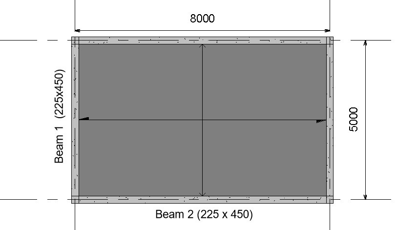
Design Data:
Imposed load on slab = 5KN/m2
Finishes = 1.5KN/m2
Unit weight of concrete = 24KN/m3
Compressive strength of concrete (fcu) = 25N/mm2
Characteristic Strength of main reinforcement (fy) = 460N/mm2
Characteristic Strength of Shear reinforcement (fyv) = 460N/mm2
To design Beam 1, we will first distribute the slab load on the beam and then analyze the beam to compute its internal forces.
To understand the process of distributing slab load to beams in detail, read, “Distribution of Slab loads to beams.”
Analysis
Dead Load
Characteristic Self-weight of slab = 0.2 x 24 = 4.8KN/m2
Partition Load on Slab = 1.5KN/m2
Characteristic Permanent Load on Slab = 4.8 + 1.5 = 6.38KN/m2
Area of Slab load Supported by Beam 1 = 0.5 x 1 x 2.5 = 1.258m2
Characteristic Permanent Load of Slab on Beam 1 = 1.258 x 6.38 = 8.02KN/m
Self-weight of beam = 0.23 x 0.45 x 24 = 2.48KN/m
Total dead Load on beam = 8.02 +2.4 = 10.42KN/m
Live Load
live load on slab = 5KN/m2
Area of Slab load Supported by Beam 1 = 0.5 x 1 x 2.5 = 1.258m2
Characteristic Live Load of Slab on Beam 1 = 1.258 x 5 = 6.25KN/m
Total Design Load
Ultimate Load acting on Slab =1.4(10.42) + 1.6(6.25) = 24.43KN/m
Computation of Internal Forces:
The beam is assumed to be simply supported for ease of analysis.
M = wL2/8 = 24.43 x 52 /8 = 76.9KNm
V = wL/2 = 23.44 x 5/2 = 61KN
Design
flexural strength design
- Calculate the effective depth
Assumptions
Cover = 25mm
Main reinforcement diameter = 16mm
Diameter of links = 10mm
Effective depth = h-c-ᴓ-ᴓ/2
= 450-25-10-16/2
= 407mm
2) Check whether section is to be designed as singly or doubly reinforced beam
$
K\,=\,\,\frac{M}{bd^2f_{cu}}
$
$
K\,=\,\,\frac{76.9×10^6}{225×450^2×25}
$
= 0.08
Since K (0.08) < K’ (0.156); design as singly reinforced.
3) Calculate the lever arm (Z)
$
Z\,\,=\,\,d\left( 0.5+\sqrt{\text{0.25}-\,\,\frac{K}{0.9}} \right)
$
$
Z\,\,=\,\,407\left( 0.5+\sqrt{\text{0.25}-\,\,\frac{0.08}{0.9}} \right)
$
Since 365 < 0.95d (386.7): use Z = 365
4. Calculate the area of steel
$
A_{s\,\,=\,\,\frac{M}{0.87f_{y}Z}}
$
$
A_{s\,\,=\,\,\frac{76.9×10^6}{0.87x460x365}}
$
As = 525.8mm2
Provide 3Y16 (599.8mm2)
5) Check Whether area of tensile steel provided satisfies minimum area requirement
Asmin = 0.0013bd
= 0.0013 x 225 x 407
= 131.625mm2
Since Ast > Asmin, minimum area requirement satisfied
6) For practical purpose of forming a reinforcement cage, provide compression reinforcement as secondary reinforcement which will serve as hanger bars
Asc = 0.002×599.8
=202.5mm2
Provide 2T12 (224.9mm2)
Read also: Design of a Singly Reinforced Beam to Eurocode 2 – Worked Example
Shear Strength Design
- Calculate the Shear Stress
- v = V/bd
- $\frac{61×10^3}{225×407}\,\,\,\,$
- = 0.67N/mm2
- $\frac{61×10^3}{225×407}\,\,\,\,$
- v = V/bd
- Check whether the concrete section can resist the shear force without shear reinforcement.
$
v_{c\,\,=}\,\,\text{0.79}\left( \frac{100As}{b_vd} \right) ^{\text{1/}3}\frac{\left( \frac{400}{407} \right) ^{\text{1/}4}}{\gamma _m}
$
$
v_{c\,\,=}\,\,\text{0.79}\left( \frac{100 x 525.8}{225 x 407} \right) ^{\text{1/}3}\frac{\left( \frac{400}{407} \right) ^{\text{1/}4}}{1.5}
$
vc = 0.52N/mm2
Since Vc (0.52N/mm2) is less than V (0.67N/mm2) then shear reinforcement has to be designed for.
3. Check the form of shear links to be provided according to table 3.7.
0.5vc = 0.5 x 0.52 = 0.26N/mm2
vc + 0.4 = 0.52 + 0.4 =0.92 N/mm2
Since 0.5vc < v < vc+0.4; minimum shear links is required according to table 3.7
4. Calculate the required minimum shear links.
Assume two-legged shear reinforcement of 10mm is to be used.
Area of 10mm shear reinforcement = 78.58mm2
Area of two-legged 10mm links = 2x 78.58 = 157mm2
$
Using: Asv_{\min}=\,\,\frac{\text{0.4}x\,\,b_v\,\,x\,\,s_v}{0.9fy_v}\,\,
$
$
Asv_{\min}=\,\,\frac{\text{0.4}x\,\,225\,\,x\,\,s_v}{0.9 x 460}\,\,
$
Since Asv = 157mm2 ; make sv the subject of the formular
sv = 763mm
5) Check whether maximum spacing limit is satisfied
Smax = 0.75xd
= 0.75 x 407
= 305mm
Since 763mm is greater than maximum spacing limit, maximum spacing limit governs the design.
Hence: provide Y10 @ 300mm spacing.
Deflection Check
Deflection Check
- Calculate the actual span-effective depth ratio
Span/depth ratio = 5000/407 = 12.3
2. Calculate the limiting Span-effective depth ratio
From table 3.9 of BS 8110, the basic Span/depth ratio for a simply supported beam is 20.
Since basic span-effective depth ratio (20) is greater than the actual span-effective depth ratio, the beam passes deflection check.
Reference(s)
BS 8110:1:1997 – Code of practice for design and construction
Thanks for sharing. I read many of your blog posts, cool, your blog is very good.
Can you be more specific about the content of your article? After reading it, I still have some doubts. Hope you can help me.
Thank you for your sharing. I am worried that I lack creative ideas. It is your article that makes me full of hope. Thank you. But, I have a question, can you help me?
Elevate Your Performance to New Heights with Meldonium
Dear Peoples,
In the relentless pursuit of excellence, whether it’s on the athletic track, in the realm of
academics, or within the high-pressure world of professional
pursuits, the margin between success and second place can be razor-thin. We
understand the unyielding desire to push beyond your
limits, to transform good into great, and great into extraordinary.
That’s why we are reaching out to you about Meldonium, also known as Mildronate,
a cutting-edge solution designed to amplify your performance, ensuring that “Whatever you do, you do better and more successfully.”
shop.toxylact.com/product/meldonium-low-price/
Meldonium stands as a beacon for those striving for peak performance.
As a synthetic analog of gamma-butyrobetaine, this potent compound is more than just a supplement; it is
a gateway to unlocking your untapped potential. Its
unique pharmacodynamics offer cytoprotective and cardioprotective benefits, meticulously engineered to optimize your body’s
energy use. By shifting the cellular metabolism from fatty acid oxidation to glycolysis, Meldonium ensures a more efficient energy use under
stress, propelling you towards achieving your goals with unparalleled
vigor.
The swift absorption and prompt action of Meldonium, reaching peak plasma concentrations within 1-2 hours of administration, make it an ideal ally in your quest for excellence.
With indications for the treatment of various cardiac and cerebrovascular disorders, it also stands as a testament to
our commitment to not only enhancing your performance but also safeguarding your health.
However, greatness requires precision. Meldonium is recommended for individuals beyond the constraints of severe hepatic
impairment, hypersensitivity, pregnancy, lactation, and those under
18. Adhering to the recommended dosage of 500-1000 mg per
day for cardiac conditions and 500 mg per day for cerebrovascular disorders, underlines our
dedication to your health and well-being.
Side effects, although rare, can include tachycardia, changes in blood pressure, and more, emphasizing the importance of adherence
to prescribed guidelines and consultations with healthcare professionals.
Imagine a life where your mental and physical faculties are heightened,
where your achievements are not just celebrated but marveled at.
Meldonium is your stepping stone to this reality.
Embrace the chance to redefine the limits of what’s possible.
Because with Meldonium, whatever you do, you do it better and more successfully.
Elevate your performance. Elevate your life. With Meldonium.
Yours in pursuit of excellence,
Dimitar Kehayov MD, PhD
P.S. Please kindly note that we receive and orders at WhatsApp or Viber at:
00359884777799
Excellent blog here! Also your website loads up very fast!
What web host are you using? Can I get your affiliate link to
your host? I wish my website loaded up as quickly as yours lol
Very rapidly this web site will be famous among all
blog visitors, due to it’s pleasant articles or reviews
Article writing is also a fun, if you be acquainted
with after that you can write otherwise it is complex to write.
Hi, i think that i saw you visited my blog thus i came
to “return the favor”.I am attempting to find things to enhance my site!I suppose its ok to use a few of
your ideas!!
I do not even understand how I ended up right here,
however I thought this submit was great. I do not recognize who
you might be but certainly you are going to a famous blogger if you happen to aren’t
already. Cheers!
An impressive share! I have just forwarded this onto a colleague
who had been conducting a little research on this.
And he actually bought me dinner simply because I found it
for him… lol. So allow me to reword this…. Thank YOU for the meal!!
But yeah, thanks for spending time to talk about this issue here on your blog.
This is a good tip especially to those new to the blogosphere.
Brief but very precise info… Appreciate your sharing this one.
A must read post!
This website truly has all the information I wanted concerning this subject and didn’t know who to ask.
My spouse and I absolutely love your blog and find the majority of your post’s
to be just what I’m looking for. Would you offer guest writers to write content for you?
I wouldn’t mind producing a post or elaborating on a lot of the subjects you write related to here.
Again, awesome website!
Very nice article, exactly what I needed.
Hi to all, how is the whole thing, I think every one is getting more from this website,
and your views are fastidious designed for new people.
An outstanding share! I have just forwarded this onto a coworker who was
doing a little research on this. And he in fact ordered me lunch due to the fact that I found it for him…
lol. So allow me to reword this…. Thanks for the meal!!
But yeah, thanx for spending the time to talk about this topic
here on your site.
Article writing is also a fun, if you be acquainted with afterward you can write if not
it is difficult to write.
Hello! I could have sworn I’ve been to this blog
before but after going through many of the posts I realized it’s new to me.
Nonetheless, I’m certainly happy I stumbled
upon it and I’ll be bookmarking it and checking back often!
Pretty! This was an extremely wonderful article. Thanks for supplying this info.
Hello, I think your site might be having browser compatibility
issues. When I look at your blog site in Firefox, it looks fine but when opening
in Internet Explorer, it has some overlapping. I just wanted to give you a quick heads up!
Other then that, superb blog!
Way cool! Some very valid points! I appreciate you writing this article and the rest of the site is really good.
Thanks for sharing your thoughts. I really appreciate your efforts and I
will be waiting for your further write ups thank you once again.
I am extremely impressed with your writing skills and also with the layout on your weblog.
Is this a paid theme or did you modify it yourself?
Anyway keep up the nice quality writing, it is rare to see
a nice blog like this one these days.
I’ve been exploring for a little for any high-quality articles or weblog posts on this sort of space .
Exploring in Yahoo I at last stumbled upon this site.
Reading this info So i’m happy to express that I have a very
excellent uncanny feeling I found out just what I needed.
I such a lot definitely will make sure to do not omit this
web site and give it a glance on a constant basis.
I go to see each day a few web pages and websites to read articles or reviews,
except this web site provides quality based posts.
Thanks on your marvelous posting! I truly enjoyed reading it,
you may be a great author. I will ensure that I bookmark your blog and may come back at some point.
I want to encourage you to ultimately continue your great work, have a nice day!
Nice weblog right here! Additionally your website loads up fast!
What host are you the usage of? Can I am getting
your associate link on your host? I want my web
site loaded up as quickly as yours lol
Hello everyone, it’s my first pay a visit at this site, and article is genuinely fruitful
in favor of me, keep up posting these types of articles or reviews.
When some one searches for his necessary thing, so he/she wishes to be available that in detail,
so that thing is maintained over here.
I couldn’t refrain from commenting. Very well written!
Fantastic beat ! I wish to apprentice even as you amend your
website, how can i subscribe for a weblog site? The account aided
me a appropriate deal. I have been tiny bit acquainted
of this your broadcast offered bright clear idea
Hello there! I simply would like to offer you a big thumbs
up for the excellent info you’ve got here on this post.
I am returning to your web site for more soon.
Hey! Quick question that’s entirely off topic.
Do you know how to make your site mobile friendly? My site looks weird when browsing from my iphone4.
I’m trying to find a template or plugin that might be able to resolve
this issue. If you have any suggestions, please share.
Thank you!
Hello Dear, are you truly visiting this site regularly, if so then you will absolutely get nice knowledge.
Wow, incredible weblog structure! How long have you been blogging for?
you make running a blog glance easy. The whole glance of your site is magnificent, as smartly as the content material!
Aw, this was an incredibly nice post. Taking the time and actual effort to produce
a very good article… but what can I say… I put things off a lot and don’t manage to get nearly
anything done.
Hi there, I enjoy reading all of your article post.
I wanted to write a little comment to support you.
Pretty element of content. I just stumbled upon your website and
in accession capital to claim that I acquire actually
enjoyed account your blog posts. Any way I will be subscribing to your augment and even I achievement you get right of entry to constantly quickly.
Hello! I’m at work surfing around your blog from my new iphone 3gs!
Just wanted to say I love reading through your blog and look forward to all your posts!
Carry on the superb work!
I will right away snatch your rss feed as I can not
find your e-mail subscription link or newsletter
service. Do you’ve any? Please let me understand in order that I may subscribe.
Thanks.
I have read some just right stuff here. Definitely price bookmarking for revisiting.
I surprise how a lot effort you place to create the sort of great informative site.
Hi! I could have sworn I’ve visited this web site before but after looking at a few of the posts I realized it’s new to me.
Anyways, I’m definitely delighted I came across it and
I’ll be bookmarking it and checking back frequently!
I’m more than happy to discover this website. I want to to thank you for ones time just for this wonderful read!!
I definitely liked every part of it and I have you book marked to check out new things in your
website.
Hello mates, its enormous paragraph regarding cultureand completely explained, keep
it up all the time.
Hello there! I could have sworn I’ve been to this website before but
after reading through some of the post I realized it’s new to
me. Nonetheless, I’m definitely glad I found it and I’ll be book-marking and checking back often!
These are in fact enormous ideas in on the topic of blogging.
You have touched some good factors here.
Any way keep up wrinting.
Incredible! This blog looks just like my old one!
It’s on a totally different subject but it has pretty much the same layout and design. Outstanding
choice of colors!
hello there and thank you for your info – I’ve definitely picked up something new
from right here. I did however expertise some technical points using this website,
as I experienced to reload the site a lot of times previous to I could get it to load correctly.
I had been wondering if your web hosting is OK? Not that
I’m complaining, but sluggish loading instances times will
sometimes affect your placement in google and could damage your quality score if advertising and marketing with Adwords.
Well I am adding this RSS to my e-mail and could
look out for much more of your respective interesting content.
Make sure you update this again soon.
Do you have any video of that? I’d like to find out more details.
Hey I know this is off topic but I was wondering if you knew of any widgets
I could add to my blog that automatically tweet my newest twitter updates.
I’ve been looking for a plug-in like this for quite some time and was hoping maybe you would have some experience with
something like this. Please let me know if you run into anything.
I truly enjoy reading your blog and I look forward to your new updates.
Hmm it appears like your blog ate my first comment (it was extremely long) so I guess I’ll just
sum it up what I had written and say, I’m
thoroughly enjoying your blog. I as well am an aspiring
blog blogger but I’m still new to the whole thing. Do you have any tips for first-time blog writers?
I’d genuinely appreciate it.
Hi there, just became alert to your blog through Google, and found that it’s really informative.
I am going to watch out for brussels. I will be grateful if you continue this in future.
Many people will be benefited from your writing. Cheers!
We are a group of volunteers and starting a new scheme in our community.
Your web site provided us with valuable info to work on. You have done a formidable job and our whole community will be thankful to
you.
Hey! I realize this is somewhat off-topic however I needed
to ask. Does building a well-established blog such as yours require a large amount
of work? I am completely new to operating a blog however I do write in my journal every day.
I’d like to start a blog so I can easily share my personal experience and views online.
Please let me know if you have any ideas or tips for brand new aspiring blog owners.
Appreciate it!
Hey! This post could not be written any better!
Reading this post reminds me of my good old room mate! He always kept chatting about this.
I will forward this write-up to him. Fairly
certain he will have a good read. Thank you for sharing!
I am regular reader, how are you everybody? This post posted at this web site is
in fact nice.
This page certainly has all of the information and facts I needed concerning this subject and didn’t
know who to ask.
Hey very nice blog!
For most up-to-date information you have to pay a quick visit internet and on internet I found this
site as a finest web page for latest updates.
When someone writes an article he/she keeps the idea of a user in his/her mind that how a user can understand it.
So that’s why this piece of writing is perfect. Thanks!
You are so interesting! I don’t believe I have
read through anything like this before. So wonderful
to discover someone with original thoughts on this subject matter.
Seriously.. thanks for starting this up. This website is something that is needed on the
internet, someone with a bit of originality!
What a stuff of un-ambiguity and preserveness of valuable know-how on the topic
of unpredicted emotions.
I pay a visit everyday some web pages and information sites to read articles or reviews, except this blog provides feature
based posts.
This is very interesting, You’re an excessively professional blogger.
I have joined your feed and look ahead to looking for extra of your wonderful post.
Additionally, I’ve shared your website in my social networks
Aw, this was an incredibly good post. Finding the
time and actual effort to make a great article… but what can I say…
I procrastinate a lot and don’t seem to
get anything done.
If you would like to take much from this piece of writing
then you have to apply such methods to your won blog.
Hey There. I found your blog using msn. This is a really
well written article. I will make sure to bookmark it and
come back to read more of your useful information. Thanks for the post.
I will definitely comeback.
Вы можете легко и бесплатно скачать видео с YouTube, VK, OK, RuTube, Mail, Dzen и многих других сайтов без торрент torrent magnet, только прямые ссылки.
Przykładem bonusu powitalnego może być promocja – 100% bonus od pierwszego depozytu ze a hundred darmowych spinów.
Pretty nice post. I just stumbled upon your blog and wished to say that I have truly
enjoyed browsing your blog posts. In any case I will be subscribing to your rss
feed and I hope you write again very soon!
Hi there mates, pleasant article and pleasant urging commented at
this place, I am truly enjoying by these.
Attractive element of content. I just stumbled upon your weblog and in accession capital to assert that I
get actually enjoyed account your blog posts.
Anyway I will be subscribing for your feeds and even I success you get entry to consistently
rapidly.
This piece of writing is genuinely a fastidious one it assists new web visitors, who are
wishing for blogging.
At this time it sounds like WordPress is the best blogging platform out there right now.
(from what I’ve read) Is that what you are using on your blog?
Have you ever thought about including a little bit more
than just your articles? I mean, what you say is fundamental and all.
However imagine if you added some great visuals or
videos to give your posts more, “pop”! Your content is excellent but with
pics and clips, this website could definitely be one of the most beneficial in its niche.
Excellent blog!
Hi there, I enjoy reading through your article post.
I wanted to write a little comment to support you.
This is a topic that is close to my heart… Take care!
Where are your contact details though?
bookmarked!!, I love your blog!
This is very interesting, You are a very skilled
blogger. I have joined your feed and look forward to seeking more of your magnificent post.
Also, I have shared your website in my social networks!
В целом, удобство использования платформы Unlim Casino на высшем уровне.
Balloon Casino также привлекает пользователей своей системой бонусов и акций.
Лобби здесь поражает разнообразием игр от проверенных производителей ПО, включая традиционные слоты, игры с живыми дилерами и симуляторы настольных развлечений.
Для казино Vavada долгое время приоритетными остаются игроки из России, Украины, Казахстана, Беларуси других стран СНГ и Европейского Союза.
Write more, thats all I have to say. Literally, it seems as though
you relied on the video to make your point. You clearly know what youre talking about,
why waste your intelligence on just posting videos to your blog when you could
be giving us something informative to read?
I love your blog.. very nice colors & theme. Did you make this website yourself or did you
hire someone to do it for you? Plz answer back as I’m looking
to construct my own blog and would like to know where u got this from.
many thanks
I loved as much as you’ll receive carried out right
here. The sketch is attractive, your authored subject matter stylish.
nonetheless, you command get bought an impatience over that you wish
be delivering the following. unwell unquestionably come more
formerly again since exactly the same nearly a lot often inside
case you shield this increase.
Hello, I read your new stuff daily. Your humoristic style is awesome, keep up the good work!
I must thank you for the efforts you have put in writing this website.
I’m hoping to check out the same high-grade blog posts by you later on as well.
In fact, your creative writing abilities has encouraged me to get my very own blog now 😉
Oh my goodness! Awesome article dude! Thank you so much, However I
am encountering troubles with your RSS. I don’t know the reason why
I cannot subscribe to it. Is there anyone else getting the
same RSS issues? Anybody who knows the answer will you kindly respond?
Thanks!!
Thank you for the good writeup. It actually used to be a amusement account it.
Glance advanced to more brought agreeable from you!
However, how could we keep in touch?
hello there and thank you for your information – I have certainly picked up anything new from right here.
I did however expertise several technical issues using this website, since I experienced
to reload the website many times previous to I could get it to load correctly.
I had been wondering if your web host is OK? Not that I am complaining, but sluggish loading instances times will
very frequently affect your placement in google and could damage your high quality score if advertising and marketing with Adwords.
Well I am adding this RSS to my e-mail and could look out for
a lot more of your respective exciting content.
Ensure that you update this again very soon.
индивидуальные проститутки мытищи порно фильмы со смыслом
жены шлюхи гей эскорт ростов на дону ебля тайских шлюх
Thank you for the auspicious writeup. It in fact was a amusement account it.
Look advanced to far added agreeable from you! However, how could we communicate?
Incredible! This blog looks exactly like my old one!
It’s on a completely different topic but it has pretty much the same layout and design. Wonderful choice of colors!
Nice post. I learn something totally new and challenging on sites I stumbleupon on a daily
basis. It will always be exciting to read articles from other writers and use
something from other websites.
We stumbled over here by a different page and thought I
might as well check things out. I like what I see so i am just
following you. Look forward to looking over your web page repeatedly.
What’s up, after reading this awesome paragraph i am too glad to share my know-how
here with friends.
Excellent post. I was checking continuously this blog and I am inspired!
Very useful info specially the ultimate part 🙂 I take
care of such info much. I was looking for this particular info for a
long time. Thank you and good luck.
Wow! This blog looks just like my old one! It’s on a entirely different topic but it
has pretty much the same layout and design. Great choice of colors!
I love reading an article that will make men and women think.
Also, thank you for allowing me to comment!
For most up-to-date news you have to visit world-wide-web and on the web I found this web
page as a finest website for latest updates.
Link exchange is nothing else but it is only placing the other person’s web site link on your page at proper place and
other person will also do similar in support of you.
If some one wants expert view concerning blogging afterward i propose him/her to pay a visit
this web site, Keep up the fastidious job.
Wonderful article! We are linking to this great post on our website.
Keep up the good writing.
You can definitely see your skills in the work you write.
The world hopes for even more passionate writers such as you
who are not afraid to mention how they believe. At all times follow your heart.
Definitely imagine that that you stated. Your favorite justification appeared to be on the web the simplest thing to consider of.
I say to you, I definitely get annoyed while
folks think about worries that they plainly don’t recognise about.
You managed to hit the nail upon the highest and defined out the whole thing without having side-effects , folks can take a signal.
Will likely be back to get more. Thanks
Pretty! This was a really wonderful post. Thanks for supplying this information.
I’ll immediately seize your rss as I can’t to find your email subscription hyperlink or newsletter service.
Do you’ve any? Please permit me recognise so that I may just subscribe.
Thanks.
It’s very effortless to find out any topic on web as
compared to textbooks, as I found this post at this
website.
Thanks for another excellent post. Where else may just anybody get that kind of info in such an ideal manner of writing? I’ve a presentation next week, and I’m at the search for such information.