Column design charts are created to simplify the design of reinforced concrete columns. These charts are published by British Standard Institution (BSI) and are available in part 3 of BS 8110. They are applicable to rectangular columns with symmetrical arrangement of reinforcement. Each chart is suitable to certain columns with peculiar parameters which are:
- Characteristic strength of concrete (fcu)
- Characteristics strength of reinforcement (fy)
- Ratio between the effective depth and column height. (d/h)
The charts are available for columns of concrete grade 25, 30, 35, 40, 45, and 50. They are available in d/h ratio between 0.75 and 0.95 at 0.05 increments. The reinforcement grade for which they are applicable is 460N/mm2.
Worked Example
This article presents a worked example on how to design a column using these charts. The column that shall be designed is column EF which has been previously analysed as part of a frame using moment distribution method. The moment in the column has been obtained already and it has been evaluated to be 11.2KNm. We are left with evaluating the axial load on the column.
The axial force of a column in a structural frame may be calculated on the assumption that the beams and slabs transmitting force into the particular column are simply supported. By this, the reaction from the column can be calculated which in turn serves as the load on the column. The reaction on the column shall be calculated as follows:
We shall first provide the subframe below for easy reference.

From basic load take down technique, column EF supports half of the load acting on both Beams BE and EH. Since the load acting on Beams BE and EH are 207.5 and 117.6 respectively, then the column reaction is:
207.5/2 + 117.6/2 = 162.55KN
Having calculated the axial load on the column, we can now proceed to write down the loads and other design parameters necessary for the column design.
Moment on the column (M2) = 11.2KNm
Axial load on the column (N) = 162.55 KN
Length = 4m
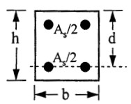
b = 300mm
h = 350mm
fcu = 25N/mm2
cover = 25mm
Steps in designing the column
-
Check the Slenderness of the column.
The slenderness ratio of the column shall be compared against the limiting slenderness, if the slenderness ratio is greater than the limiting slenderness then the column is declared “slender”. The column is declared “short” if otherwise. This is shown in the below steps
-
Calculate the effective height of the column
Since the column is braced, the Effective height (lo) is calculated thus:
le = β lo
a) Calculate the clear height (lo) of the column
lo (clear height of the column) = 4000 – 600 x 0.5 – 600 x 0.5 = 3400mm
(The clear height of the column is the obvious height of the column between end restraints. In this case, the clear height of the column is taken to midway of the depth of both top and bottom beams framing into the column)
b) Evaluate the relative stiffness at the column ends
β is a coefficient dependent on the end condition of the column. Its value can be obtained from table 3.19 and 3.20 of BS 8110-1:1997, however a rigorous approach will be adopted here according to clause 2.5 of BS 8110-2: 1985.
According to BS 8110 part 2, for braced column B is adopted as the lesser of:
β = 0.7 + 0.05(αc1 + αc2)
β = 0.85 + 0.05αcmin
αc2 and αc1 are the relative flexibilities of the top and bottom ends respectively
αc2 = $
\frac{\frac{\varSigma I_c}{l}}{\frac{\varSigma EI_b}{l}}
$
$
\frac{\frac{\frac{bh^3}{12}}{l}}{\frac{\frac{bh^3}{12}}{l}\,\,+\,\,\frac{\frac{bh^3}{12}}{l}}
$
$
\frac{\frac{\frac{300 X 350^3}{12}}{4000}}{\frac{\frac{300 X 600^3}{12}}{6000}\,\,+\,\,\frac{\frac{300 X 600^3}{12}}{6000}}
$
= 31525.35/(900000 + 900000)
= 0.175
We do the same thing all over again to get αc1
αc1 = $
\frac{\frac{\varSigma I_c}{l}}{\frac{\varSigma EI_b}{l}}
$
$
\frac{\frac{\frac{bh^3}{12}}{l}}{\frac{\frac{bh^3}{12}}{l}\,\,+\,\,\frac{\frac{bh^3}{12}}{l}}
$
$
\frac{\frac{\frac{300 X 350^3}{12}}{4000}}{\frac{\frac{300 X 600^3}{12}}{6000}\,\,+\,\,\frac{\frac{300 X 600^3}{12}}{6000}}
$
= 31525.35/(900000 + 900000)
= 0.175
β = 0.7 + 0.05(0.175 + 0.175) = 0.7175
β = 0.85 + 0.05 x 0.175 = 0.8588
Adopt the lesser as
β = 0.7175
c. Determine the effective height
l = β lo
l = 0.7175 x 2439.5 = 2439.5
2. Compare the slenderness ratio against the limiting slenderness.
lex/h and ley/b < 15 – braced column
lex/h = 2439.5/350 = 6.97
ley/b = 2439.5/300 = 8.13
Since lex/h and ley/b are less than 15 then the column is short and additional moment due to slenderness is not required.
3. Compute the design moment (M)
The design moment is the greater between the end moment (M2) and the moment due to nominal eccentricity (Nemin)
emin = 0.05 X h (≤ 20mm)
emin = 0.05 X 350 (≤ 20mm)
emin = 17.5mm (≤ 20mm)
Since 17.5mm is less than 20mm, the minimum eccentricity is taken as 17.5mm
Nominal moment= 0.00175 X 162.55 = 0.28KNm
Since the minimum moment (0.28KNm) is less than M2(11.2KNm), hence the critical moment to be adopted for the design is 11.2KNm
4. Use the design Chart to determine the area of longitudinal reinforcement required
In order to use the design chart, few parameters have to be calculated;
a. Determine N/bh
N/bhf = 162.55 X 10^3 /300 X 350 = 1.55
b. Determine M/bh²
M/bh² = 14.451 X 10^6/300 X 350² = 0.4
c. Calculate d/h
d/h determines the exact graph that shall be used to determine the reinforcement area.
d = h- c + ϕ/2 + ϕ
= 350 – 25 – 10 – 8
d/h = 307/350 = 0.88
This is approximated to 0.9 and the design chart with parameters which conforms with d/h = 0.9, fcu = 25N/mm2, and fy = 460N/mm2 is used. Chart 25 in BS 8110 Part 3 matches this. The chart is reproduced below.

From the design chart, the intersection of M/bh² = 0.4 and N/bh = 1.55 falls below the 0.4 mark. This implies there is no need to provide reinforcement for the column. However, to keep to BS 8110 directives minimum area of reinforcement shall be provided.
100Asc/Acol = 0.4
As = 0.004 X 300 X 350
As = 420mm2
Hence provide 4Y12 (449.856mm2) as the longitudinal reinforcement of the column
5. Determine the size of links required and spacing
a. Link diameter
The link diameter is the greater of;
- ¼ x maximum diameter of longitudinal bar
- 6mm
¼ x maximum diameter of longitudinal bar = ¼ x 12 = 3mm
Hence use 6mm as the link diameter.
b. Link Spacing
The link spacing should not be greater than 12 x minimum diameter of longitudinal bar
- 12 x minimum diameter of longitudinal bar = 12 x 12 = 144mm
Provide 6mm links at 125mm spacing.
I’m really enjoying the design and layout of your blog. It’s a
very easy on the eyes which makes it much more pleasant for me to
come here and visit more often. Did you hire out a designer to create your
theme? Exceptional work!
Right now it sounds like WordPress is the preferred blogging platform
available right now. (from what I’ve read) Is that what you are
using on your blog?
Undeniably believe that which you said. Your favorite reason seemed to be
on the internet the simplest thing to be aware of.
I say to you, I certainly get irked while people think about worries that they just do not know about.
You managed to hit the nail upon the top as well as defined
out the whole thing without having side effect , people could take a signal.
Will probably be back to get more. Thanks
If some one desires to be updated with most up-to-date technologies therefore he must be pay a quick visit this website and be
up to date everyday.
I like what you guys are usually up too. This kind
of clever work and exposure! Keep up the terrific works guys I’ve
you guys to blogroll.
Hello my loved one! I wish to say that this post is amazing, nice written and include
almost all vital infos. I’d like to see more posts
like this .
I have been browsing online more than 3 hours today, yet I never found any interesting article like yours.
It’s pretty worth enough for me. In my view, if all web owners and bloggers made good
content as you did, the internet will be much more useful than ever before.
hi!,I love your writing so so much! share
we keep up a correspondence more about your article on AOL?
I need a specialist on this area to resolve my problem.
Maybe that’s you! Having a look ahead to see you.
great publish, very informative. I ponder why the opposite experts of this sector don’t realize this.
You should proceed your writing. I am sure, you’ve a huge readers’ base already!
Pretty nice post. I just stumbled upon your blog and wished to
say that I have really enjoyed browsing your blog posts.
In any case I will be subscribing to your rss feed and I hope you write again soon!
I really like your blog.. very nice colors & theme. Did you create this website yourself or did
you hire someone to do it for you? Plz reply as I’m looking to create my
own blog and would like to find out where u got this from.
thanks
I know this web site offers quality based content and other material, is there any other site which presents these things in quality?
Its like you learn my mind! You appear to grasp so much approximately this, like you wrote the ebook in it or
something. I feel that you simply can do with a few p.c. to power the message home a bit, but instead of that, this is great blog.
A great read. I will definitely be back.
We’re a group of volunteers and starting a new scheme in our community.
Your web site provided us with valuable information to
work on. You have done a formidable job and our entire
community will be grateful to you.
WOW just what I was searching for. Came here by searching for website
Heya i am for the first time here. I found this
board and I find It truly useful & it helped me out a lot.
I hope to give something back and help others like you helped me.
This paragraph presents clear idea in favor of the new people of blogging,
that truly how to do blogging.
This website definitely has all the info I needed concerning this subject and didn’t know who to ask.
I have read so many articles or reviews about the
blogger lovers except this paragraph is genuinely a nice piece of writing, keep it up.
Hello There. I discovered your weblog the usage of msn. This is a very well written article.
I will make sure to bookmark it and return to read more of your helpful information. Thanks for the post.
I’ll certainly comeback.
I need to to thank you for this fantastic read!! I absolutely
loved every bit of it. I have got you book marked to look at new things
you post…
At this moment I am going to do my breakfast, when having my
breakfast coming yet again to read further news.
Simply want to say your article is as astonishing.
The clearness in your post is just great
and i can assume you are an expert on this subject. Well with your permission let me
to grab your feed to keep up to date with
forthcoming post. Thanks a million and please carry on the enjoyable work.
Incredible quest there. What happened after? Take care!
I think this is one of the such a lot important info for
me. And i am happy reading your article. However wanna remark on few common things, The
web site style is perfect, the articles is in reality great : D.
Excellent task, cheers
I’m amazed, I must say. Rarely do I encounter a blog that’s both equally
educative and amusing, and let me tell you,
you have hit the nail on the head. The problem is something too few people
are speaking intelligently about. I am very happy that
I came across this during my search for something relating to this.
I’m amazed, I have to admit. Seldom do I come across a blog that’s
both educative and amusing, and let me tell you, you’ve hit the nail on the head.
The issue is something too few folks are speaking intelligently about.
Now i’m very happy I came across this in my search for something regarding this.
This site was… how do you say it? Relevant!!
Finally I’ve found something that helped me. Thanks a lot!
You made some decent points there. I checked on the internet for additional information about
the issue and found most people will go along with your views on this
site.
I like what you guys are usually up too. This sort of clever work and exposure!
Keep up the awesome works guys I’ve you guys to my own blogroll.
It is in reality a great and useful piece
of info. I am satisfied that you shared this
useful information with us. Please stay us up
to date like this. Thank you for sharing.
Hello are using WordPress for your site platform? I’m new to
the blog world but I’m trying to get started and create my own. Do you require any
coding expertise to make your own blog? Any help would be really appreciated!
I must thank you for the efforts you have put in penning this website.
I’m hoping to see the same high-grade content by you later on as well.
In truth, your creative writing abilities has inspired me to get my own, personal site now 😉
After looking over a handful of the articles on your site, I really appreciate your way
of writing a blog. I saved it to my bookmark webpage list and will be checking back soon. Take a look at my web site too and tell
me your opinion.
I think this is one of the most significant information for me.
And i am glad reading your article. But wanna remark on some general things,
The web site style is perfect, the articles is really excellent
: D. Good job, cheers
Hello my friend! I wish to say that this post is awesome, great written and include approximately all important infos.
I’d like to peer more posts like this .
At this moment I am ready to do my breakfast, when having my breakfast
coming yet again to read more news.
My spouse and I stumbled over here different website and thought I might check things out.
I like what I see so now i am following you.
Look forward to finding out about your web page repeatedly.
First off I want to say fantastic blog! I had a quick question that I’d like to ask if you do not
mind. I was curious to know how you center yourself and clear your mind before writing.
I’ve had a tough time clearing my mind in getting my thoughts
out. I do take pleasure in writing but it just seems
like the first 10 to 15 minutes are generally wasted simply just trying to figure out how
to begin. Any ideas or tips? Cheers!
My relatives always say that I am wasting my time here at web, however I know I am getting
knowledge daily by reading thes nice articles.
This paragraph is really a fastidious one it helps new the web viewers, who
are wishing in favor of blogging.
Hello everyone, it’s my first go to see at this website, and
article is really fruitful in support of me, keep up posting these
articles or reviews.
Excellent beat ! I wish to apprentice at the same
time as you amend your website, how could i subscribe for a weblog web site?
The account aided me a appropriate deal. I have been a
little bit acquainted of this your broadcast offered vivid clear idea
I visit daily some web pages and websites to read content, but this webpage offers quality based writing.
I believe that is one of the most vital information for me.
And i am happy reading your article. However want to statement on few general issues, The
web site style is wonderful, the articles is actually nice : D.
Just right task, cheers
Yes! Finally someone writes about joker123 pulsa.
What a data of un-ambiguity and preserveness of precious experience concerning unpredicted
emotions.
I’d like to find out more? I’d want to find out some additional information.
I’m amazed, I have to admit. Seldom do I encounter
a blog that’s both equally educative and amusing, and let me tell
you, you have hit the nail on the head. The problem is
something which too few folks are speaking
intelligently about. I am very happy I found this during my hunt for something concerning this.
whoah this weblog is great i like studying your articles.
Keep up the good work! You know, many persons are searching around for this
info, you can aid them greatly.
Your mode of telling everything in this article is truly pleasant, every
one can without difficulty be aware of it, Thanks a lot.
I’m really inspired together with your writing skills and also with the layout for your weblog.
Is that this a paid subject matter or did you customize
it yourself? Anyway stay up the excellent high quality writing,
it is uncommon to peer a nice weblog like this one nowadays..
I’m excited to find this web site. I wanted to thank you for your time for this fantastic
read!! I definitely enjoyed every little bit of
it and i also have you book marked to check out new things
in your website.
Hi there! Quick question that’s totally off topic.
Do you know how to make your site mobile friendly? My weblog looks weird when browsing from my apple iphone.
I’m trying to find a template or plugin that might be able
to resolve this problem. If you have any
recommendations, please share. With thanks!
Great blog here! Also your web site loads up very fast!
What web host are you using? Can I get your affiliate link to your host?
I wish my web site loaded up as quickly as yours lol
Hello there! Do you use Twitter? I’d like to follow you if that would
be okay. I’m undoubtedly enjoying your blog and look forward to new updates.
This is my first time pay a quick visit at
here and i am actually impressed to read everthing at single place.
It’s awesome designed for me to have a website, which is
valuable for my experience. thanks admin
Whats up are using WordPress for your site platform? I’m new to the blog world but I’m trying to get started and create
my own. Do you require any html coding expertise to make your own blog?
Any help would be greatly appreciated!
Hello! This is kind of off topic but I need some
help from an established blog. Is it very hard to set up your own blog?
I’m not very techincal but I can figure things out pretty fast.
I’m thinking about setting up my own but I’m not
sure where to start. Do you have any ideas or suggestions?
Thank you
This is really interesting, You’re a very skilled blogger.
I have joined your rss feed and look forward
to seeking more of your great post. Also, I’ve shared
your web site in my social networks!
You’re so interesting! I don’t suppose I have read a single thing like
that before. So wonderful to discover somebody with some genuine thoughts
on this subject matter. Really.. many thanks for starting this up.
This web site is one thing that is required on the web, someone with some
originality!
I used to be recommended this blog through my cousin. I’m no longer positive
whether this post is written through him as no one else recognize
such particular approximately my difficulty. You’re wonderful!
Thanks!
For latest information you have to go to see world
wide web and on the web I found this web page
as a best web site for newest updates.
Link exchange is nothing else however it is simply placing the
other person’s webpage link on your page at proper place
and other person will also do similar in favor of you.
I think this is one of the most vital information for me.
And i am glad reading your article. But want to remark on few general
things, The web site style is wonderful, the articles
is really nice : D. Good job, cheers
Very energetic blog, I loved that a lot. Will there be a part
2?
Hi there, yup this piece of writing is genuinely fastidious
and I have learned lot of things from it regarding blogging.
thanks.
you are actually a good webmaster. The web site loading speed is incredible.
It seems that you’re doing any distinctive trick. Also, The contents are masterpiece.
you have performed a magnificent job in this matter!
Hello, I desire to subscribe for this webpage to take latest
updates, therefore where can i do it please help.
I visited various websites but the audio quality for audio songs current at this web site is actually wonderful.
This is really fascinating, You’re a very professional blogger.
I have joined your feed and look forward to seeking more of your wonderful post.
Additionally, I have shared your site in my social networks
Having read this I believed it was extremely informative.
I appreciate you spending some time and energy to put this short article
together. I once again find myself spending a lot of time
both reading and leaving comments. But so what, it was still worthwhile!
Hi there, I check your blogs on a regular basis. Your writing
style is awesome, keep it up!
Hi there just wanted to give you a quick heads up. The words in your
content seem to be running off the screen in Opera. I’m not sure if this is
a format issue or something to do with internet browser compatibility but I figured I’d post
to let you know. The style and design look great
though! Hope you get the issue solved soon. Cheers
Оно является совершенно новым азартным ресурсом, запущенным в сентябре 2023 года.
Например, игроки могут получать фриспины и другие выгодные предложения по средам и понедельникам.
Можно использовать Биткоин и другие криптовалюты для покупки предметов коллекционирования.
This post will help the internet users for building up new webpage
or even a blog from start to end.
Существование такой лицензии не имеет никакого значения, так как все остальные параметры также бессмысленны.
Разнообразие доступных игр и турниров также дает возможность опробовать разные подходы и стили игры.
My spouse and I absolutely love your blog and find the majority of your post’s to be exactly what I’m looking for. Does one offer guest writers to write content to suit your needs? I wouldn’t mind creating a post or elaborating on many of the subjects you write about here. Again, awesome site!
шлюхи в центре города порно голодная девочка на секс порно знакомство в калининграде откровенную порно игру скачать