This article presents a detailed overview on wind load on bridges to EN 1991-1-4-2005 and UK Annex to EN 1991-1-4-2005 + A1:2010.
This article shall build on a previous article titled “Wind Actions on Structures” where a detailed explanation is made on the steps required to calculate wind peak velocity pressure. If you do not have a thorough background on wind actions, it is recommended that you visit the previous article and read up to “peak velocity pressure” before continuing with this article.
In “Wind Actions on Structures” the steps required to determine wind forces on a structure are broadly categorized into three. The first category is about determining the wind velocity. The second category becomes conclusive on determining the peak velocity pressure. The third category which is “calculation of wind forces on a structure” has been explained to be structure specific (ie: it depends on the type of structure). The main aim of this article is to revisit this third category in light of bridge structures, which is domiciled in section 8 of EN 1991: 1-4.
Limitations specific to Bridges
Besides the general scope of EN 1991-1-2005 stated in clause 1.1 (2) which have been highlighted in the previous article, additional limitation of types of bridge considered in the standard is stated in Section 8.
According to Clause 8.1, the standard is only applicable to
- Bridges having no span greater than 200m (This is in addition to the limit that the structure must not be higher than 200m)
- Bridges of constant depth and with classical cross-sections such as slab bridge, girder bridge, box girder bridge, truss bridge etc.
- Bridges which are not subjected to aerodynamic phenomena and does not require dynamic response procedure. Further details on assessing dynamic response of bridges are discussed below.
Overriding information when determining the peak velocity pressure
In determining the peak velocity of wind for bridge structures, the below two information overrides that stated in the previous article in the same manner the information in section 8 of the standard supersedes, when necessary, information in the previous sections as regards computation of wind forces on bridges.
- Fundamental wind velocity: Where road traffic is considered to be simultaneous with the wind (see A2.2.1 and A2.2.2 in Annex A2 to EN 1990) the combination value Ѱ0Fwk of the wind action on the bridge and on the vehicles should be limited to a value Fwk determined by substituting a value vb,o for the fundamental value of the basic velocity vb,O. The recommended value of vb,o is 25m/s by the standard
The UK national annex has a different approach. It maintains vb,O as the fundamental wind velocity but limit the value of peak velocity to 750 Pa.
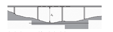
- Reference height for peak velocity Pressure: The reference height ( ze) for the peak velocity pressure is taken as the distance from the lowest ground level to the center line of the bridge deck structure, disregarding other parts of the reference areas as shown below.
Dynamic Response of Bridges
According to EN 1991-1-4, dynamic response procedure is generally not needed for normal (bridges constructed in steel, concrete, aluminum or timber, including composite construction, and whose shape of cross sections is typical) bridge decks of less than 40 m span. Further details and criteria for assessing the significance of dynamic response is generally pass on to National Annexes. The UK NA give detail criteria for assessing the significance dynamic response of bridge from clause NA.2.43 to NA.2.46.3
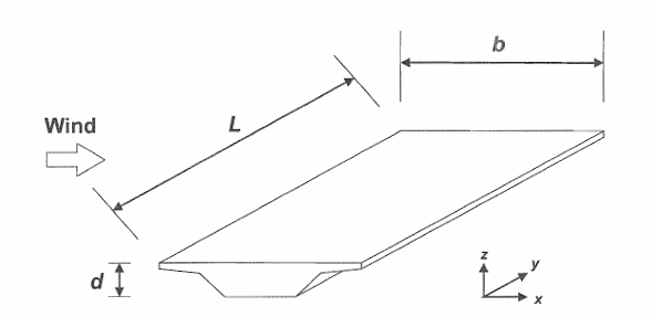
Dimension of Bridge Decks for Wind Action
The significant dimensions of the bridge deck are:
L length in y-direction
b width in x direction
d is depth in z-direction
Wind Load Effects and directions
Before diving deeper into the study of wind action on bridges, it should be noted that as a fundamental approach wind forces are determined in three directions, which are:
- X -direction
- Y-direction
- Z-direction
As shown in the figure above, the x- axis is parallel to the deck width, y-axis is parallel to the span in the plane of the deck and the z-axis is perpendicular to the deck.
The simultaneous occurrence of wind in x- and y-direction is quite rare so the simultaneous effects of wind in the two directions are always ignored. However, wind force in z-direction occurs as a result of wind in many directions which could also be either x or y. So, in principle, depending on direction of wind that produce the most critical effects in z-direction, winds are to be considered simultaneously on x- and z-direction or y-and z-direction.
However, in practice, between these two combinations of directions, wind forces are mostly determined simultaneously in x-and z-direction as this are most likely to be critical. In fact, the standard only considers wind force in y-direction to be some calculated percentage of that in x-direction. Consequently, the x-direction can be said to be the principal direction of wind force on bridge structures. If the effect of wind in z-direction is adjudged to be uncritical, wind force can be determined only in x-direction.
Wind force in x-direction
Wind force on bridge structures in x-direction can be determined by either of the two procedures below:
- General Method
- Simplified method
The General Method
The general method is a developed procedural method that follows the steps discussed in the previous article till determining the peak velocity pressure. The result of the product of the peak velocity pressure with appropriate directional parameters such as force coefficient (cfx) and reference area (Arefx) give the wind force in the direction of interest.
The expression for determining the wind force in x -direction is:
Fw= cscd cfx qp(Ze) Arefx
Where:
cscd is the structural factor and this can be taken as 1
qp(Ze) is the peak velocity pressure (read the previous article on how to calculate the peak velocity pressure.)
Arefx is the reference area for wind force in x-direction which shall be discussed subsequently
cfx is the force coefficient for wind force in x-direction, which is discussed below.
Force Coefficients in x-direction
The force coefficient of wind force in x-direction is generally referred to as drag coefficient. It is given as:
cfx = cfx,o
Where:
cfx,o is the force coefficient without free-end flow.
In most practical cases bridges are always without free-end flow as they are always continuous even over abutment, so the wind flow is only deviated over and under the bridge. The value of cfx,o can be taken as 1.3 or determined using figure 8.3 of the standard.
The value of force coefficient in the standard either determined from figure 8.3 or taken as 1.3 is only valid when the angle of inclination of the wind is between -10 and 10. If the angle exceeds this then a wind tunnel test or other alternative special studies is required to determine the drag coefficient
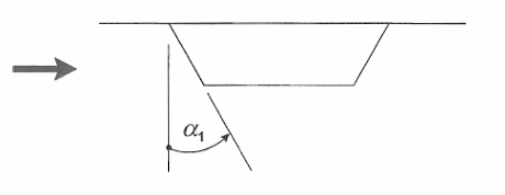
Where the windward face of the bridge is inclined to the vertical (see the figure below), the drag coefficient cfx,0 may be reduced by 0.5% per degree of inclination limited to a maximum reduction of 30%. Where a bridge deck is sloped transversally, cfx,o should be increased by 3% per degree of inclination, but not more than 25%.
The Simplified Method
The simplified method does not require that the peak velocity pressure is determined. Only the basic wind velocity (vb) together with the wind load factor (C) and reference area (Arefx) is required to determine wind forces as shown is the below expression.
Fwk = 1/2 ρ vb2CArefx
Where:
ρ is the density of air
vb is the basic wind velocity
C is the wind load factor. Its value can be determined from table 8.2 of the standard. (The UK NA recommends that the value of C is taken from table NA.7)
Arefx is the reference area for wind in x-direction
Reference Area for Wind Force in x-direction
Whether a simplified method or general method is adopted in estimating wind load on a bridge, the reference area is a common parameter to be evaluated. The reference area of bridge in x-direction is considered for two cases:
- For load combinations without considering traffic load on the bridge
- For load combination where traffic load on the bridge is considered.
Reference Area when traffic load on the bridge is not considered
The reference Area is given by the expression
Arefx = b x dtot
Arefx is the reference area in x-direction
b is the breadth of the bridge
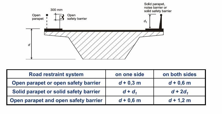
dtot is the depth of the part of the bridge which are considered to be subjected to the wind pressure. In the case of the bridge in service without consideration of the traffic, dtot is the sum of the projected (windward) depth of the structure, including the projecting solid parts, such as footway or safety barrier base, plus 0.3m for the open safety barrier in each side of the deck. This is described in fig 8.5 and table 8.1 of the standard which are reproduced below.
Reference Area when traffic load on the bridge is considered
The reference area formular remains as described above where traffic load is not considered. The breadth of the bridge remains the same. However, for road bridges, a height of 2 m from the level of the carriageway, on the most unfavorable length, independently of the location of the vertical traffic loads.
Wind force in z-direction
The wind force in the z-direction tends to uplift the bridge structure. The expression for determining the wind force in z -direction is:
Fw= cscd cfz qp(Ze) Arefz
Where:
cscd is the structural factor and this can be taken as 1
qp(Ze) is the peak velocity pressure (read the previous article on how to calculate the peak velocity pressure.)
Arefz is the reference area for wind force in z-direction which shall be discussed subsequently
cfz is the force coefficient for wind force in z-direction, which is discussed below.
Force Coefficients in z-direction
The force coefficient of wind force in z-direction is generally referred to as lift force coefficient (cfz). The National Annex may give values for cfz, In the absence of wind tunnel tests the recommended value may be taken equal to ±0,9. This value takes globally into account the influence of a possible transverse slope of the deck, of the slope of terrain and of fluctuations of the angle of the wind direction with the deck due to turbulence.
As an alternative may be taken from Figure 8.6 of the standard. In using it:
- The depth dtot may be limited to the depth of the deck structure, disregarding the traffic and any bridge equipment
- for flat, horizontal terrain the angle of the wind with the horizontal may be taken as +-5degrees due to turbulence. This is also valid for hilly terrain when the bridge deck is at least 30 m above ground.
- No end-effect factor should be taken into account.
- The reference height is the same as for cfz
- If not otherwise specified, the eccentricity of the force in the x-direction may be set to e = b/4.
Reference Area for Wind Force in z-direction
The reference area for wind load in z direction is the area of the bridge on plan, which is:
Arefz = b x L
Where:
b is the length of the bridge
L is the length of the bridge
Wind forces on bridge decks in y-direction
As stated earlier, the wind force in y-direction is calculated as percentage of wind force in x-direction, hence no special parameter is required to calculate wind force in this direction if it is at all necessary.
The recommended values are:
- for plated bridges, 25 % of the wind forces in x-direction,
- for truss bridges, 50 % of the wind forces in x-direction.
The UK NA gives alternative procedure to determine wind load in y-direction. This can be found in clause NA.2.51 of the National Annex
Wind Load on Bridge Piers
Bridge piers should be considered for wind load during persistent design situation and also during transient design situation. The transient design situation is often critical for wind loads for obvious reasons. During construction phases, the horizontal transmission or redistribution of wind actions is not possible due to the absence of bridge deck. Another area where the determination of wind actions on piers is important is for the design of foundations.
The effects of wind load on bridge pier should be considered for the most onerous direction for appropriate design. Bridge piers can be designed for wind load depending on their shapes using provisions in various clauses as specified below:
Clause 7.6 – bridge piers of rectangular sections
Clause 7.8 – bridge piers of regular polygonal section
Clause 7.9.2 – bridge piers of circular cylinders
The UK National Annex provides simplified Rules for bridge piers. Upper bound values of the force coefficient Cfp for piers are provided in Table NA.8. These values have been based on BS EN 1991-1-4:2005 7.6 using an end-effect factor for a value of 2 ⋅ height/breadth.