This article presents guidance on how to allow for imperfections in analysis of RC frames according to EN 1992-1-1 (Eurocode 2).
Structural frames in reality are always marred with imperfections which are deviations from idealized state of the structure during simulations. Imperfections could be as a result of deviation in cross-section dimension of a member, it could also be as a result of deviation in material properties such as when concrete of slightly different grade from engineer’s specification is achieved on site. These types of imperfections are always allowed for by partial factors of safety during designs. However, deviations in geometry during execution and uncertainty in position of axial load are not catered for by material partial safety factors, and must be catered for exclusively during analysis or design as geometric imperfections. Hence, EN 1992-1-1 provides guidance on allowing for geometric imperfection in section 5.2 of the standard.
Idealization of Imperfection
Imperfections on any structure or member can be idealized as an inclination ϴ1 given by:
φ = φ0αhαm
where;
φ0 is the basic value 1/200
αh is the height reduction factor
αh = 2/√l (but 2/√3 ≤ αh ≤ 1.0)
l is the length or height of the structure
αm is the reduction factor for number of vertical members. αm = √(0.5 (1 + 1/m))
m is the number of vertical members contributing to the total effect
In the above expression for imperfection, the definition of l and m depends on the effect considered, for which three main cases can be distinguished
Effect on isolated member: l = actual length of member, m =1.
Effect on bracing system: l = height of building, m = number of vertical members contributing to the horizontal force on the bracing system.
Effect on floor or roof diaphragms distributing the horizontal loads: l = storey height, m = number of vertical elements in the storey(s) contributing to the total horizontal force on the floor.
Guide to modelling Imperfections
Imperfections should ordinarily be catered for in structures by modelling these structures out-of-plumb. This approach, however, would be rather tedious and time consuming especially for complex multi-storey frames. To avoid this, rather than modelling these imperfections in a frame it would be better to represent these imperfections with an equivalent effect. Subsequent sections below provide guidance according to Eurocode 2 on how to model these effects in (1) A structure as a whole, (2) Isolated slender elements (3) elements which transfer forces to bracing members such as diaphragms.
Effects of Imperfection in Structures
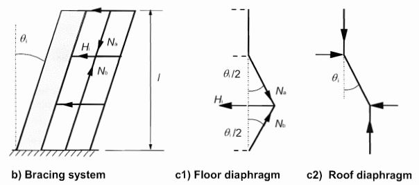
For structures, the effect of imperfection (ϴ1) may be represented by transverse forces (H), which is to be combined with other actions in the analysis of the structure. The transverse fore (H) is the product of the imperfection and vertical forces in the system. The transverse force can be applied to the structure through floor diaphragm or bracing system.
Expressions for the transverse force for different method of application on structure is given below:
For bracing system
Hi = θ1 (Nb – Na)
For floor diaphragm
Hi = θ1 (Nb + Na)/2
For roof diaphragm
Hi = θ1 (Nb + Na)/2
This transverse force that simulates the effects of imperfections is similar to what is termed equivalent horizontal force (EHF) in EN 1993-1-1. You can click here to see a demonstrated example on how this transverse force (EHF in EN 1993-1-1) can be applied on structures using Etabs software.
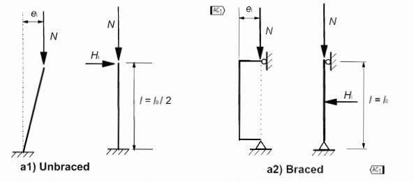
Effects of Imperfection in Isolated members as Eccentricity
For isolated members, the effect of imperfections may be taken into account as eccentricity given as:
ei = θ1 lo/2
for simplification can be taken as 1 so that θ1 = 1/200
ei = lo/400
Then the moment generated by this eccentricity is:
M = θ1 ei = NEd lo/400
This eccentricity due to imperfection should however not be less than minimum eccentricity in a column or wall which is h/30
Click here to study a worked example on the design of column to Eurocode 2 where this eccentricity due to imperfection is applicable.