
This article presents a practical worked example on the design of unrestrained steel beam (I-section) to Eurocode 3
The beam to be designed has been analysed using Etabs software as part of a frame in the article, ”Analysis of Steel Frames Allowing for Imperfections”, the resulting bending moment and shear force diagram are shown below.
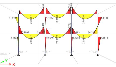
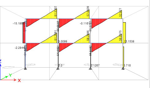
Internal forces
From the analysis results, the maximum of the internal forces acting on each beam shall be considered to be acting on the beam to be designed.
Maximum Shear Force = 61.53KN (left topmost beam)
Maximum Moment = 37.347KNm (left lower beam)
Beam Properties
Beam section: 457 x 152 x 52 UKB S275
The properties of the steel section listed below are excerpted from SCI P363
h = 449.8mm, b = 152.4mm, tw= 7.6mm, tf = 10.9mm, r = 10.2mm, d = 407.6mm, iy = 17.9cm, iz = 3.11cm, Wply = 1100cm³, Wplz = 133cm³, A = 66.6cm², E = 210 x 103cm3, Iy =21400cm4, Iz = 645cm4, Iw= 0.311dm6, It = 21.4cm³
cf/tf = 5.71
cw/tw = 53.6
Cross-section Classification
We shall classify the cross-section of the beam (you should click here to study a detailed article on cross-section classification of steel cross-sections).
Influence of material strength
The UK National Annex recommends that EN 10025-2:2004 replaces Table 3 of EN 1993-1-1:2005 to determine the yield strength (fy) and ultimate strength (fu) of steel sections
Hence, for thickness of 10.9mm for grade S275 |fy = 275MPa, fu = 430MPa (Table 7, EN 10025-2)
$$
\varepsilon \,\,=\,\,\sqrt{\frac{235}{275}}\,\,=\,\,0.925
$$
Flanges (Outstand Element)
Since the neutral axis of the section is assumed to be within the web, the flange is in pure compression.
(Using Table 5.2 (Sheet 2 of 3) of EN 1993-1-1-2005)
cf/tf = 5.71mm
from the table, limiting value for class 1 is 9 ℇ = 9 x 0.925 = 8.325
since 5.71 < 8.325, the flanges are class 1
Web (Internal Element)
(Using Table 5.2 (Sheet 1 of 3) of EN 1993-1-1-2005)
cw/tw= 53.6
from the table, limiting value for class 1 is 72ℇ = 72 x 0.925 = 66.6
since 53.6 < 66.6, the web is class 1
The entire cross-section is class 1 in bending.
Cross-section Resistance
The column cross-section shall be verified for resistance to Shear and bending.
Shear Resistance
The expression below has to be satisfied for the section to be adequate in shear
$$
\,\,\frac{V_{Ed}}{V_{cRd}}\,\,\leqslant \,\,1
$$
$
\,\,V_{c,Rd}\,\,=\,\,V_{pl,Rd}\,\,=\,\,\frac{A_v\,\,f_y/\sqrt{3}}{\gamma _{m0}}
$
For rolled I and H sections: Av = A – 2btf + (tw + 2r)tf ≥ ηhwtw
Av = 66.6 x 10² – 2 + (7.6+ 2 x 10.2) x 10.9 ≥ η(449 – 2 x 10.9)7.6
Av = 3642.88 ≥ 3252.8
Av = 3642.88
Check
61.52/57.38 = 0.106
Since 0.106 ≤ 1 the section is adequate in shear
Bending Resistance
For adequate moment resistance, the equation below should be satisfied.
$
\,\,\frac{M_{Ed}}{M_{cRd}}\,\,\leqslant \,\,1
$
$
\,\,Mc,Rd\,\,=\,\,Mpl,Rd\,\,=\,\,\frac{W_{ply}.\,\,f_y\,\,}{\varUpsilon _{m0}}\,\,\,\,
$ (for class 1, and class 2 sections)
$
\,\,Mc,Rd\,\,=\,\,\frac{1100 x 10^3 .\,\,275\,\,}{1 x 10^6}\,\,\,\,
$ = 302.5KNm
Check
37.347/302.5 = 0.12
Since 0.12 ≤ 1, the section is adequate in bending
Combined Shear and Bending Resistance
The maximum bending moment and shear force acts occur at the end of each beam, hence the maximum shear force shall be adopted as coincidence shear.
We shall check whether reduction in bending resistance is necessary due to the shear force.
0.5 Vpl,Rd = 0.5 x 578.38 = 289.19KN
Since VEd ≤ 0.5Vpl,Rd , then reduction in bending resistance is unnecessary
The section is adequate for combined bending and shear.
Stability Check
If the beam were restrained, we would have rounded off the design after verifying the combined shear and bending resistance, however the beam is un-restrained hence we have to verify its stability against lateral torsional buckling
Verify the Resistance of the Beam to Lateral torsional buckling
Lateral torsional buckling is evaluated using the expression below:
$$
M_{b,Rd}\,\,=\,\,\chi _{LT}\,\,\frac{W_y\,\,.\,\,f_y}{\varUpsilon _m}
$$
Where,
$
\,\,\chi _{LT}\,\,=\,\,\frac{1}{\phi _{LT}\,\,+\,\,\sqrt{\phi _{LT}^2\,\,+\,\,\ βλ _{LT}^2}}
$
ΦLT = 0.5 (1 + ∝LT( λLT – λLT,0) + βλLT ²)
$
\,\lambda _{LT}\,\,=\,\,\sqrt{\frac{W_y\,\,.\,\,f_y}{M_{cr}}}
$
Calculate the Elastic Critical Moment
$M_{C r}=C_1 \frac{\pi^2 E I_z}{L^2} \sqrt{\frac{I_w}{I_z}+\frac{L^2 G I_t}{\pi^2 E I_z}}$
C1= 2.578 (This is the value of C1 for transverse loaded member with the shape of bending moment as shown above. Click here to study in detail the theory and fundamental concept of lateral torsional buckling)
G = 80770 N/mm²
E = 21000
Iw = 0.311dm6, It = 21.4cm³
Iz = 645cm4
L = 4000mm
$M_{C r}= 1.77 \frac{3.142^2 x 210000 x 645 x 10^4} {4000^2 x 10^3} \sqrt{\frac{0.311 x 10^12}{645 x 10^4}+\frac{4000^2 x 81000 x 21.4}{3.142^2 x 210000 x 645}}$
Mcr= 565.779
Calculate the Non-dimension Slenderness
$
\,\lambda _{LT}\,\,=\,\,\sqrt{\frac{1100 x 10^3\,\,.\,\,275}{565.779 x 10^6}}
$ = 0.731
h/b = 2.95, use buckling curve c (Table 6.5, EN 1993-1-1)
∝LT = 0.49 (using Table 6.5)
β = 0.75
λLT,0 = 0.4
ΦLT = 0.5 (1 + 0.49(0.731– 0.4) + 0.75 x 0.731²) = 0.782
Calculate the reduction factor
$
\,\,\chi _{LT}\,\,=\,\,\frac{1}{0.782\,\,+\,\,\sqrt{0.782^2\,\,+\,\,\ 0.75 x 0.731^2}}
$ = 0.807
Mb,Rd = 0.807 x 302.5 = 243.98KNm
Since 0.153 ≤ 1, the section is adequate
Check
$
\,\,\frac{M_{Ed}}{M_{bRd}}
$ = $
\,\,\frac{37.347}{243.98}
$ = 0.153
Since 0.153 ≤ 1, the section is adequate
Deflection Check
Maximum deflection for fixed beam = $
\,\,\frac{FL^4}{384EI}
$ =
F = live load = 30KN/m, L = 4000mm
Maximum deflection = $
\,\,\frac{30 x 10^3 x 4^4}{384 x 210 x 10^9 x 21400 x 10^-8}
$ x 10³ = 0.445
Limiting for beams = span/200 = 4000/200 = 20mm (Table NA.2, UK NA EN 1993-1-1)
Since 0.445 ≤ 20, then deflection criterium is satisfied.


