This article provides an overview of the design of combined footing. At the end of the article, a practical worked example is presented on the design of combined footing supporting three columns. The foundation was sized ensuring the line of action of column forces and centroid of the base coincides. This foundation is then modelled and analysed in CSI SAFE software. The analysis results are then used to design the foundation to EN 1992:1-1.
A combined footing is a foundation that supports more than one column in a line, ensuring safe distribution of their loads to the ground. This type of footing is often adopted in a situation where columns are so close such that adopting an isolated pad footing will cause an overlap of the footings. These columns to be supported are always on a single longitudinal direction. When a single foundation supports grid of columns in both longitudinal and transverse direction then such foundation is referred to as a mat foundation.
Another form of combined foundation is strap foundation; this is adopted when a column is close to a boundary line or other existing structures such that an isolated base would be encroaching. In such a scenario, it would be necessary that the column foundation at the boundary line is combined with adjacent isolated foundation with a beam so that its footing doesn’t have to be spread beyond the boundary line. The strapping beam offsets the centroid of the boundary column and ensures it does not overturn over its base.
Steps in designing combined foundation
- Size the foundation such that the centroid of the loads coincides with the centroid of the foundation. This ensures the bearing pressure in the soil under the foundation is uniform. However, when this cannot be achieved due to practical constraints then the foundation should be designed for the attendant moment.
- Calculate the actual bearing pressure on the foundation
- Analyse the foundation as an inverted continuous slab such that the bearing pressure acts on it as a uniform load and the columns act as support to the slab
- Use the moment and shear forces from the analyses to design the foundation
Ensuring the resultant load from the columns passes through the centroid of the base area can be daunting. This can lead to adopting different shape of footing or even combination of elements for the foundation to achieve efficiency of load transfer. Some of these combinations are discussed below.
Types of Combined Foundations
- Slab Type Combined Foundation: A single, large rectangular or trapezoidal slab that supports multiple columns. This type of foundation is common when columns are close together and load distribution needs to be efficient. The trapezoidal slab is sometimes necessary to make the point of action of load and centroid of base coincides, it, however, comes with the consequence of cumbersome detailing and also placement of reinforcement on site.
- Slab and Beam Type Combined Foundation: This foundation consists of a slab with beams connecting the columns. The beams distribute the loads to the slab, and the slab then distributes the loads to the soil.
- Strap (or Strap-Type) Combined Foundation: This type includes a strap or connecting beam that ties two or more footings together. The strap helps distribute the load and ensures stability, particularly when columns are located at varying distances from each other.
Worked Example
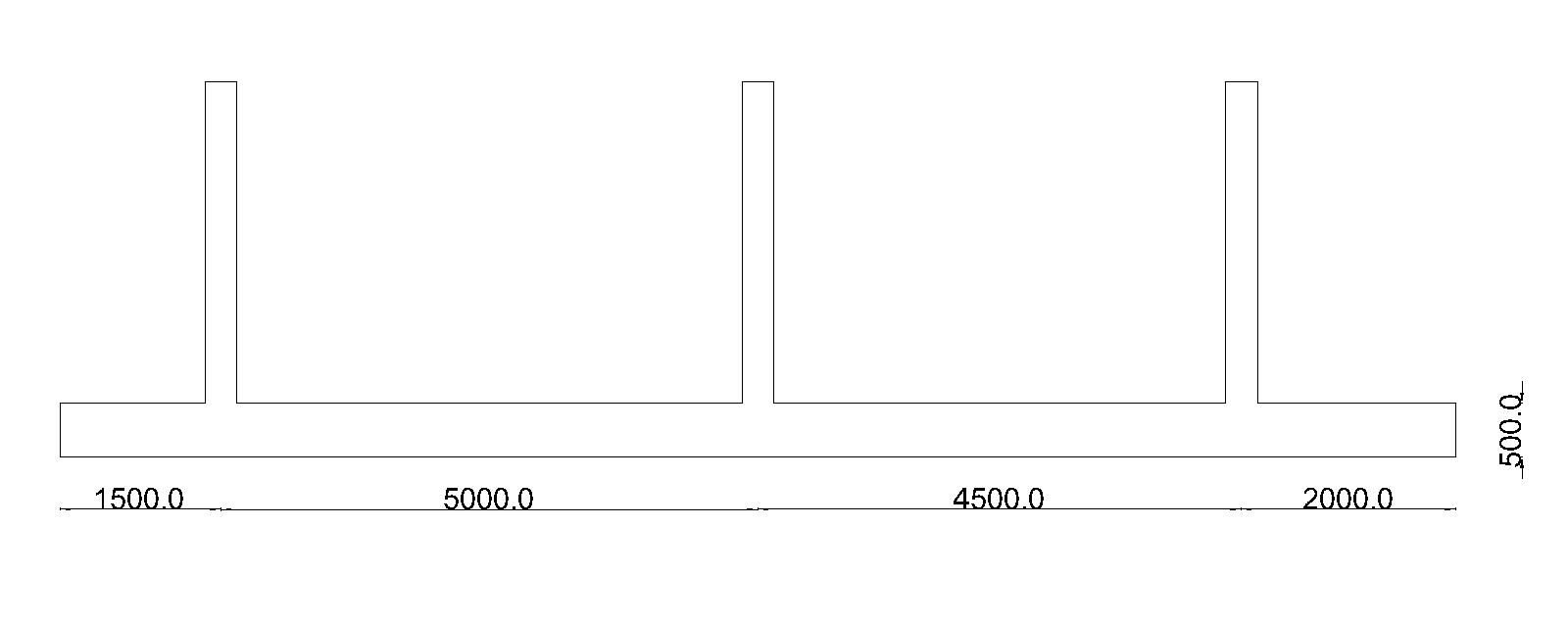
Three columns of cross-section 300 x 300mm which lie on a single line as shown below are to be provided with footings on a site in Norwich city, East of England. After geotechnical investigation, it is observed that the site contains deposit of glacial till with a bearing capacity of 100KN/m². Adopting an isolated footings results in overlapping of the footings hence a combined footing is desired. Design a combined footing for the columns.
The characteristics strength of concrete and reinforcement for the pile cap are 25MPa and 500MPa respectively.
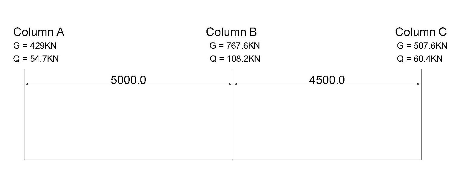
Loads on the columns
Total dead load = 429 + 767.6 + 507.6 = 1704.2KN
Total live load = 54.7 + 108.2 + 60.4 = 223.3KN
Total Service Load = 1704.2 + 223.3 = 1927.5KN
Total service load on column 1 = 483.7KN
Total service load on column 2 = 875.8KN
Total service load on column 3 = 568KN
Proportioning the Footing
The footing shall be proportioned under the columns such that uniform soil pressure develops under the footing. This shall be achieved by making the centroid of the loads coincides with the centroid of the footing. This is actualized in the steps below
Determine the centroid of the column
Take the moment of forces about the centre of column 1
1927.5 x = 875.8 x 5 + 568 x (4.5 + 5) = 5.0m
The centroid is 5.0m from column 1
Determine the Area, Length, and Breadth of the footing
Area = Total service load/ allowable bearing pressure
Area = 1927.5/100 = 19.275m²
Let’s take a footing width of 1.5m (This narrow width is adopted so that verification of punching shear at control perimeter which is 2d from the column face according to EN 1992-1-1 will not be required).
Footing length = Area/width = 19.725/1.5 = 12.85m
Take the length of the footing as 13m.
The footing has to be placed such that the centroid of the footing and load coincides as shown below:
Determine the depth of the footing
The overriding factor that determines the depth of footings is resistance to punching shear. We can generally assume a depth and check later for punching shear. However, let’s be a little detailed and choose a footing depth based on maximum shear capacity of the concrete.
VRD, max = 0.3 (1 – fck/250) fcd
fcd = fck/1.5 = 25/1.5 = 16.67 N/mm²
VRD, max = 0.3 (1 – 25/250)16.67
VRD, max = 4.5 N/mm²
The maximum punching shear capacity of the concrete without reinforcement is 4.5KN.
Then we shall equate the punching stress generated at the column perimeter of the column with highest load to this and obtain the appropriate effective depth
vEd = VEd/u x d
u1 = 2(C1 + C2) = 2(300 + 300) = 1200mm
Maximum load = 1.5 x 875.8 = 1313.7KNm
4.5 = (1313.7 x 10³)/ (1200 x d)
d = 243.3
We can add allowance for cover of 50mm and round up the height of the footing to be 300mm. However, we shall go for a greater height to lower the reinforcement requirement of the foundation. We shall go for a footing of 500mm height.
Analysis of the Combined Footing
The footing can be analysed as an inverted slab where the bearing pressure of the soil acts as gravity load while the columns act as supports. The bending moment and shear force can be generated by analysing the frame using moment distribution method just like analysing a flat slab. Another alternative is to analyse it as a continuous one-way slab over supports using table 3.12 of BS 8110.
However, in this article we shall model the footing in CSI Safe software and anlayse it to generate its internal forces and moments.
Modelling and Analysis using CSI Safe
The foundation is modelled as a slab supporting the three columns. The live load and dead load patterns are defined, and combinations for both ultimate limit state and serviceability limit state are created with appropriate factors according to Eurocode 1. The soil properties are modelled using subgrade modulus by dividing the bearing capacity of the soil by allowable settlement thus:
Subgrade modulus = bearing capacity/allowable settlement
= 100/0.025 = 40000KN/mm³.
The foundation is then analysed. The analysis results are displayed below:


Design of the footing
Having analysed the foundation to generate the internal forces and moments, we shall verify the size of the foundation is adequate to safely distribute the loads from the column to the soil by checking the soil pressure. Additionally, we shall also design the footing section for reinforcement to resist internal stresses.
Check soil Pressure
The soil pressure of the foundation due to the loads on the column has to be checked. From the post analysis results in CSI Safe. The maximum soil pressure is 46.18KN/m², which is lower than bearing capacity of 100KN/m².

Design for longitudinal Support Moment
- Calculate the effective depth
Assumptions
Cover = 50mm
Main reinforcement diameter = 12mm
Effective depth = h-c-ᴓ/2
= 500-50-12/2
= 444mm
2) Check whether section is to be designed as singly or doubly reinforced beam
$ K\,=\,\,\frac{M}{bd^2f_{ck}} $
$ K\,=\,\,\frac{141 x 10^6}{1000 x 444^2 x 25} $
= 0.03
Since K (0.03) < K’ (0.168); design as singly reinforced.
3) Calculate the lever arm (Z)
$ Z\,\,=\,\,d\left( 0.5+\sqrt{\text{0.25}-\,\,\frac{K}{1.134}} \right) $
$ Z\,\,=\,\,444\left( 0.5+\sqrt{\text{0.25}-\,\,\frac{0.03}{1.134}} \right) $ = 432.5
Since 432.5 < 0.95d (421.8): use Z = 421.8
4. Calculate the area of steel
$ A_{st\,\,=\,\,\frac{M_{Ed}}{0.87f_{yk}Z}} $
$ A_{st\,\,=\,\,\frac{141 x10^6}{0.87x500x421.8}} $
Ast = 768.5mm2
Provide 8T12 @ 125c/c (899.7mm2)
5) Check Whether area of tensile steel provided satisfies minimum area requirement
Asmin = 0.26 (fctm/fyk )bt d
fctm = 0.3 x fck^(2/3) = 0.3 x 25^(2/3) = 2.57MPa
Asmin = 0.26 (2.57/500) 1000 x 444
Asmin= 592.2mm2
Since Ast > Asmin, minimum area requirement satisfied
Design for Longitudinal Span Moment
- Calculate the effective depth
Assumptions
Cover = 50mm
Main reinforcement diameter = 12mm
Effective depth = h-c-ᴓ/2
= 500-50-12/2
= 444mm
2) Check whether section is to be designed as singly or doubly reinforced beam
$ K\,=\,\,\frac{M}{bd^2f_{ck}} $
$ K\,=\,\,\frac{56.3 x 10^6}{1000 x 444^2 x 25} $
= 0.01
Since K (0.01) < K’ (0.168); design as singly reinforced.
3) Calculate the lever arm (Z)
$ Z\,\,=\,\,d\left( 0.5+\sqrt{\text{0.25}-\,\,\frac{K}{1.134}} \right) $
$ Z\,\,=\,\,444\left( 0.5+\sqrt{\text{0.25}-\,\,\frac{0.01}{1.134}} \right) $ = 432.5
Since 439.5 < 0.95d (421.8): use Z = 421.8
4. Calculate the area of steel
$ A_{st\,\,=\,\,\frac{M_{Ed}}{0.87f_{yk}Z}} $
$ A_{st\,\,=\,\,\frac{56.3 x10^6}{0.87x500x421.8}} $
Ast = 306.8mm2
5) Check Whether area of tensile steel provided satisfies minimum area requirement
Asmin = 0.26 (fctm/fyk )bt d
fctm = 0.3 x fck^(2/3) = 0.3 x 25^(2/3) = 2.57MPa
Asmin = 0.26 (2.57/500) 1000 x 444
Asmin= 592.2mm2
Since the minimum area of reinforcement is greater than area of steel required, then provide minimum area of reinforcement
Provide 6Y12@150c/c (674.8mm2)
Secondary Span Reinforcement
Provide minimum reinforcement as secondary reinforce
Provide 6Y12@150c/c (674.8mm²)
Design for transverse reinforcement
- Calculate the effective depth
Assumptions
Cover = 50mm
Main reinforcement diameter = 12mm
Effective depth = h-c-ᴓ/2
= 500-50-12/2
= 444mm
2) Check whether section is to be designed as singly or doubly reinforced beam
$ K\,=\,\,\frac{M}{bd^2f_{ck}} $
$ K\,=\,\,\frac{75.1 x 10^6}{1000 x 444^2 x 25} $
= 0.015
Since K (0.015) < K’ (0.168); design as singly reinforced.
3) Calculate the lever arm (Z)
$ Z\,\,=\,\,d\left( 0.5+\sqrt{\text{0.25}-\,\,\frac{K}{1.134}} \right) $
$ Z\,\,=\,\,444\left( 0.5+\sqrt{\text{0.25}-\,\,\frac{0.015}{1.134}} \right) $ = 438
Since 438 < 0.95d (421.8): use Z = 421.8
4. Calculate the area of steel
$ A_{st\,\,=\,\,\frac{M_{Ed}}{0.87f_{yk}Z}} $
$ A_{st\,\,=\,\,\frac{75.1 x10^6}{0.87x500x421.8}} $
Ast = 409.3mm2
5) Check Whether area of tensile steel provided satisfies minimum area requirement
Asmin = 0.26 (fctm/fyk )bt d
fctm = 0.3 x fck^(2/3) = 0.3 x 25^(2/3) = 2.57MPa
Asmin = 0.26 (2.57/500) 1000 x 444
Asmin= 592.2mm2
Since Ast > Asmin, minimum area requirement satisfied
Since the minimum area of reinforcement is greater than area of steel required, then provide minimum area of reinforcement
Provide 6Y12@150c/c (674.8mm2)
Verify Punching Shear at Column Perimeter
Calculate the punching shear stress at column perimeter
The maximum shear force on the footing at column point is 155KN
(vEd) = 𝛽 VEd/u0x d
take 𝛽 = 1.0
Column perimeter (u0) = 4 x 300 = 12000
Take the average effective depth of slab in x and y direction to be 444mm
(vEd) = (155 x 10³/ (12000 x 444) = 0.3N/mm²
Calculate the punching shear capacity of concrete
vRDmax = 0.3 (1 -fck/250)fcd
fcd = fck/1.5 = 25/1.5 = 16.67 N/mm2
vRDmax = 0.3 (1 -25/250)16.67
=4.5 N/mm²
vRDmax > vEd, the depth of slab is sufficient for punching shear.
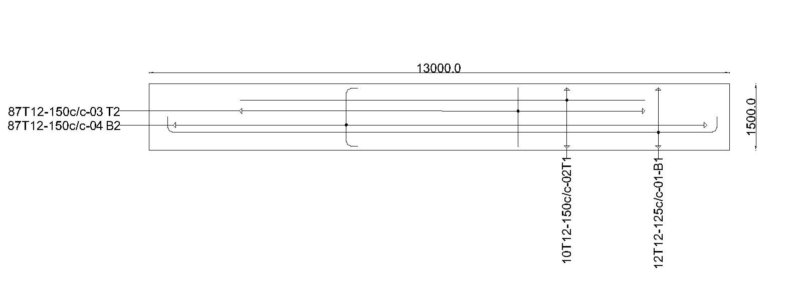
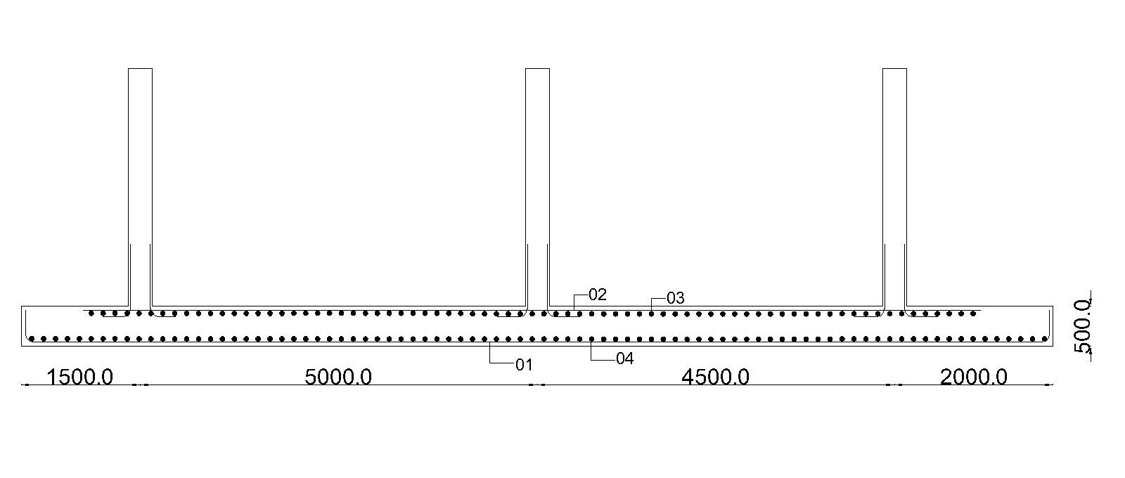
Detailing