1.0 Introduction:
Moment distribution is an iterative method of structural analysis that is used to analyze statistically indeterminate beams and frames to obtain the moments at their joints. It was developed by Hardy Cross and was first published in 1930 in ASCE journal.
2.0 Basic concepts related to Moment Distribution Method
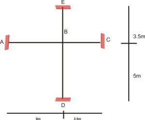
In order to successfully analyze using moment distribution method, the following concepts must be well understood. These vital concepts are treated chronologically below in that order they would be applied when analyzing using moment distribution method. Study the beam below (fig (1)) well as it will be referred to several times to explain these vital concepts.
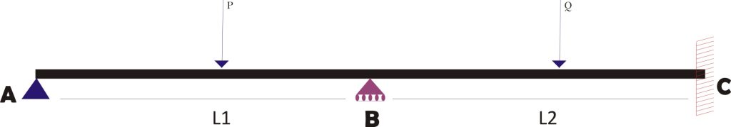
2.1 Fixed End Moment
Fixed end moment is a rotational force that is exerted on a particular end of a structural element to prevent it from rotating about that end.
When analyzing continuous beams using moment distribution method, all existing supports are first assumed to be fixed, and their fixed end moments are calculated. This is demonstrated below.
The figure below shows the discretization of each span of the continuous beam in fig (1) into single span fixed beam.
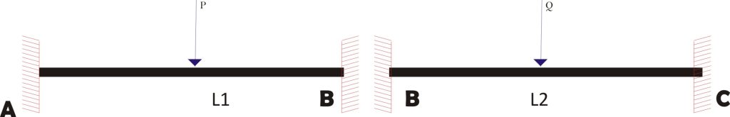
Their fixed end moments can be obtained by using the formulars below.
$
_{M_{AB\,\,}}\,\,=\,\,-\,\,\frac{P\,\,*\,\,\begin{array}{l}
L_1\\
\end{array}}{8}
$
$
_{M_{BA\,\,}}\,\,=\,\,\,\frac{P\,\,*\,\,\begin{array}{l}
L_1\\
\end{array}}{8}
$
$
_{M_{BC\,\,}}\,\,=\,\,-\,\,\frac{Q\,\,*\,\,\begin{array}{l}
L_2\\
\end{array}}{8}
$
$
_{M_{CB\,\,}}\,\,=\,\,\,\frac{Q\,\,*\,\,\begin{array}{l}
L_2\\
\end{array}}{8}
$
2.2 Bending Stiffness
Bending stiffness is the flexural rigidity of the member. It is the measure of the resistance of a member to flexural displacement or deformation. The higher the stiffness, the higher the force required to displace the member under flexural load.
The bending stiffness is dependent on four factors
- Modulus of elasticity (E)
- Second moment Area (I)
- Length of the member (L)
- The type of support of the beam.
If both end of the beam are continuous over supports or fixed, then the bending stiffness is 4EI/L. However, if either of the ends of the beam is pinned then bending stiffness reduces to three-quarter of that with fixed or continuous ends and thus become ¾ *4EI/L.
Therefore, for span AB in fig (1), the beam is continuous over the support at B but the support at A is pinned. This means either of the two supports is pinned so the stiffness of the beam is:
$
_{K_{AB\,\,}}$ = ¾ * 4EI/L
For span BC the ends are either fixed or continuous over a support so the stiffness is:
$
_{K_{BC\,\,}}$ = 4EI/L
2.3 Distribution Factors
Distribution factor determines the proportionality of the unbalance moment that is taken by each member meeting at a joint. In clear terms, when a moment is applied at a joint, the distribution factor determines how much of the moment is shared by each of the members connected to that joint. It is determined by calculating the relative stiffness of each member.
The distribution factor of a member equals the ratio of the stiffness of the member to the summation of the total stiffness of all members meeting at that joint.
From this, the distribution factor of member AB is:
$
_{D_{AB\,\,}}\,\,=\,\,-\,\,\frac{K_{A\underset{}{B}}}{K_{AB}\,\,+\,\,K_{BC}}\,\,=\,\,\,\,\frac{K_{AB}}{K_{Total}}
$
The distribution Factor of member BC is:
$
_{D_{BC\,\,}}\,\,=\,\,-\,\,\frac{K_{B\underset{}{C}}}{K_{BC}\,\,+\,\,K_{AB}}\,\,=\,\,\,\,\frac{K_{BC}}{K_{Total}}
$
2.4 Carry over moment
Carry over moment is the moment that is distributed to the remote end of a member when moment is applied to its other end. The moment carried over to the remote end is always half of the moment applied to the other end if the remote end is fixed. However, if the remote end is pinned or free, no moment is carried over.
Now let’s solve an example using the above concepts highlighted one after the other.
3.0 Worked Example: Analysis of a beam using moment distribution method
Analyze the beam below using moment distribution method.
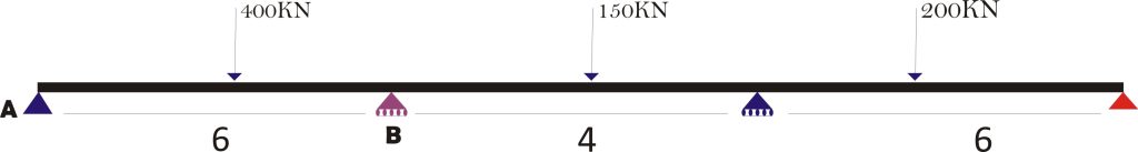
STEP 1: Assume every support in the beam is fixed and calculate the fixed end moment.
Thus:
$
_{M_{AB\,\,}}\,\,=\,\,-\,\,\frac{P\,\,*\,\,\begin{array}{l}
L\\
\end{array}}{8}
$ = $\frac{-400\,\,*\,\,\begin{array}{l}
6\\
\end{array}}{8}
$ = -300
$
_{M_{BA\,\,}}\,\,=\,\,\frac{P\,\,*\,\,\begin{array}{l}
L\\
\end{array}}{8}
$ = $\frac{400\,\,*\,\,\begin{array}{l}
6\\
\end{array}}{8}
$ = 300
$
_{M_{BC\,\,}}\,\,=\,\,-\,\,\frac{P\,\,*\,\,\begin{array}{l}
L\\
\end{array}}{8}
$ = $\frac{-150\,\,*\,\,\begin{array}{l}
4\\
\end{array}}{8}
$ = -75
$
_{M_{CB\,\,}}\,\,=\,\,\frac{P\,\,*\,\,\begin{array}{l}
L\\
\end{array}}{8}
$ = $\frac{150\,\,*\,\,\begin{array}{l}
6\\
\end{array}}{8}
$ = 75
$
_{M_{CD\,\,}}\,\,=\,\,-\,\,\frac{P\,\,*\,\,\begin{array}{l}
L\\
\end{array}}{8}
$ = $\frac{-200\,\,*\,\,\begin{array}{l}
6\\
\end{array}}{8}
$ = -150
$
_{M_{DC\,\,}}\,\,=\,\,\frac{P\,\,*\,\,\begin{array}{l}
L\\
\end{array}}{8}
$ = $\frac{200\,\,*\,\,\begin{array}{l}
6\\
\end{array}}{8}
$ = 150
STEP 2: Determine the stiffness of each member.
Recall that a beam that has both ends fixed/continuous will have stiffness equals 4EI/L, while a beam that has either of the ends pinned will have stiffness equals ¾ *4EI/L. Hence:
$
_{K_{AB\,\,}}$ = ¾ * 4EI/L = 3EI/6 = 0.5EI
$
_{K_{BC\,\,}}$ = 4EI/L = 4EI/4 – EI
$
_{K_{CD\,\,}}$ = ¾ * 4EI/L = 3EI/6 = 0.5EI
STEP 3: Determine the distribution factors.
$
_{D_{BA\,\,}}\,\,=\,\,\frac{K_{A\underset{}{B}}}{K_{AB}\,\,+\,\,K_{BC}}\,\,=\,\,\,\,\frac{K_{AB}}{K_{Total}}
$ = $\,\,\,\,\frac{0.5EI}{0.5EI\,\,+\,\,EI}\,\,=\,\,0.333
$
$
_{D_{BC\,\,}}\,\,=\,\,\frac{K_{B\underset{}{C}}}{K_{BC}\,\,+\,\,K_{AB}}\,\,=\,\,\,\,\frac{K_{BC}}{K_{Total}}
$ = $\,\,\,\,\frac{EI}{EI\,\,+\,\,0.5EI}\,\,=\,\,0.667
$
$
_{D_{CB\,\,}}\,\,=\,\,\frac{K_{C\underset{}{B}}}{K_{CB}\,\,+\,\,K_{CD}}\,\,=\,\,\,\,\frac{K_{CB}}{K_{Total}}
$ = $\,\,\,\,\frac{EI}{0.5EI\,\,+\,\,EI}\,\,=\,\,0.667
$
$
_{D_{CD\,\,}}\,\,=\,\,\frac{K_{C\underset{}{D}}}{K_{CBB}\,\,+\,\,K_{CD}}\,\,=\,\,\,\,\frac{K_{CD}}{K_{Total}}
$ = $\,\,\,\,\frac{0.5EI}{0.5EI\,\,+\,\,EI}\,\,=\,\,0.333
$
Note: The distribution factor of a fixed support is always 0. This is because the fixed support does not require a real factor to distribute moment. A fixed joint does not distribute out any moment carried-over to it to adjacent joints. It simply absorbs them all do to its rigidity.
However, the distribution factor for a pinned or free support is 1 as it distributes out all moments that is carried over to it.
Hence in the table below, 1 will be entered as distribution factor for joint A and D respectively.
The values of the calculated Fixed End Moments and Distribution factors will be entered in a table as shown below.

STEP 4: Calculate the out of Balance Moment (OBM).
To calculate the Out of Balance Moment, the difference of the moment acting at each support is obtained. This difference will give the moment required to make that joint to be stable. This moment is then multiplied by the distribution factor of each beam meeting at that point so that each beam takes moment that is only proportional to its stiffness.
At B the difference in moment is 225KNM (300 – 75), so this value (225) is afterwards multiplied by the distribution factors 0.333 and 0.667 to get 75 and 150 respectively. These values are entered into the table as shown below. You should try the same for internal support at C and compare your results with the values in the table below.

Did you attempt that?
You should, however, have noticed that 75KNm and 150KNm which are the Out of Balance Moment for joint B carry negative signs. This is because these moments are meant to counter and balance off the inherent moment at the support which is 225 (i.e.: 300 – 75 = 225). So, the out of balance moment should always take an opposing sign to the inherent moment at the joint. Cleared?
This same concept explains why the OBMs at the end supports A and D bear positive and negative signs respectively.
STEP 5: Carry Over the OBMs to remote supports
This is shown below using arrows.

Table 3
As shown above half of the moments are carried over to the remote ends. Note that no moment is carried over to the extreme supports because they are hinged. They are meant not to attract moments. This would have been different if any of the end supports is fixed, then half of the moment from a closer support would have been carried over to the support also.
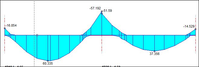
The next step is to calculate the Out of Balance Moments and repeat Step 4 and Step 5 above until the moments at the internal supports reasonably converges. If you follow the above steps diligently, your result should appear like that of the table shown in the image below.

From the above table it is observed that the values at the internal support definitely converge and the value of the moment at each internal supports sums up to zero.
The values of the moments at the extreme supports are also zeros as expected of hinge supports.
I’m amazed, I have to admit. Seldom do I encounter a blog that’s both educative and engaging,
and let me tell you, you’ve hit the nail on the head. The problem is an issue that not enough men and women are speaking intelligently about.
Now i’m very happy that I came across this during my hunt for something concerning this.
Thanks for another informative website. Where else could I get that type of info written in such
a perfect way? I’ve a venture that I’m simply now working on, and I’ve been at the glance out
for such info.
Its like you read my mind! You seem to know so much about this,
like you wrote the book in it or something.
I think that you could do with some pics to drive the message home
a little bit, but instead of that, this is excellent blog.
A great read. I will certainly be back.
Hi there, i read your blog from time to time and i own a similar one and i was just wondering if you get a lot of spam feedback?
If so how do you prevent it, any plugin or anything you can recommend?
I get so much lately it’s driving me crazy so any help
is very much appreciated.
Thanks for the comment. I really appreciate it.
I rarely receive spam feedbacks and whenever I do occasionally, they don’t get published. I already have pre-configured my comment settings to weed them out.
Very descriptive article, I loved that bit.
Will there be a part 2?
Wow, this paragraph is pleasant, my younger sister is analyzing such things, so I
am going to tell her.
I believe this is among the so much vital information for me.
And i am happy studying your article. But should remark on few general
things, The web site taste is ideal, the articles is in point of fact nice :
D. Good process, cheers
Good information. Lucky me I found your blog by chance (stumbleupon).
I’ve saved it for later!
I like it whenever people get together and share thoughts.
Great site, stick with it!
This design is wicked! You obviously know how to keep a reader entertained.
Between your wit and your videos, I was almost moved to start my own blog (well, almost…HaHa!) Wonderful job.
I really enjoyed what you had to say, and more than that, how you presented it.
Too cool!
You need to be a part of a contest for one of the best websites on the
internet. I am going to highly recommend this website!
Your article helped me a lot, is there any more related content? Thanks!
Your point of view caught my eye and was very interesting. Thanks. I have a question for you.
I have read so many articles or reviews concerning the blogger lovers but this paragraph is genuinely a nice article, keep it up.
I know this if off topic but I’m looking into starting my own weblog and was curious what all is needed to get setup?
I’m assuming having a blog like yours would cost a pretty penny?
I’m not very internet smart so I’m not 100% certain. Any tips or advice would be greatly appreciated.
Cheers
A motivating discussion is worth comment. I think that
you should publish more about this topic, it might not be a taboo
matter but typically people don’t discuss such subjects.
To the next! Cheers!!
It is not my first time to visit this website, i am
browsing this site dailly and obtain good data from here everyday.
Thanks very interesting blog!
Hi there, its nice article regarding media
print, we all understand media is a fantastic source
of facts.
Good article. I am going through a few of these issues as well..
Hi, i read your blog from time to time and i own a similar one and i was just curious if you
get a lot of spam responses? If so how do you prevent
it, any plugin or anything you can recommend?
I get so much lately it’s driving me mad so any assistance is
very much appreciated.
This article offers clear idea designed for the new people of blogging, that
really how to do blogging.
I am just commenting to let you understand what a fine discovery my friend’s daughter enjoyed reading yuor web blog. She came to find several things, which included what it’s like to have a very effective teaching mood to let the rest with ease learn selected impossible things. You undoubtedly exceeded readers’ desires. Thanks for offering such essential, safe, educational and also fun tips about the topic to Ethel.