The approach to designing reinforced concrete beam to EC2 is to design for ultimate limit state and check whether serviceability limit state criteria are met. The foremost of the ultimate limit state to design for is bending, afterwards ultimate limit state of shear is designed for and then the beam is checked for serviceability limit state of deflection. A beam is a member which has its span to be not less than 3 times the overall section depth according to clause 5.3.1 (3) of Eurocode 2. Should the span be less than 3 times the overall section depth then it is considered a deep beam. The design of a deep beam is beyond the scope of this article.
Preliminary Design
Preliminary design includes initial sizing of a beam prior to detailed design against ultimate limit state and subsequent serviceability checks. Exposure condition, concrete grade, and desired resistance against fire are from the major factors that contribute to the initial sizing of the member as they determine the amount of cover to reinforcement. In addition to the cover, other parameters that defines the geometry of a beam are the overall depth (h), breadth (b), and effective depth (d).
A reasonable value of breadth and depth of the beam can be obtained by making a few experimental calculations using any of the relevant equations for design for shear, bending moment or deflection that are given in the code.
For example, table 7.4N of the code which gives basic span-effective depth ratio can be easily employed to arrive at an initial effective depth since the span of the member would be readily picked from the structural scheme. Having gotten a suitable depth, an initial breadth can be determined using M/0.167bd2fck or using the equation for maximum shear force that can be resisted by the section.
Another approach is to assume one-third of the effective depth to be the initial breadth of the member and then proceed to detailed design accordingly.
Flexural design
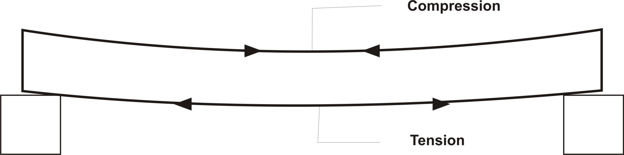
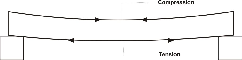
The most critical limit state for regular beams is bending. The beam is designed to successfully resist the internal bending stress that develops in the beam as a result of the effect of the external load and self-weight. This bending phenomenon, in a typical simply supported beam for example, causes the beam section above the neutral axis to be in compression while those portion below the neutral axis are subjected to tension. The tension and compression are greatest at bottommost fibers and topmost fibers of the beam respectively.
Singly and Doubly Reinforced Beam
Simply put: A singly reinforced beam is a beam that the concrete section in compression is adequate to resist the compressive stress developed in the beam due to loading without being complemented by reinforcement bars. For the beam to successfully resist compressive stress, the moment of resistance of the concrete must be larger than the moment induced in the beam by loading.
ie: Mu > MEd
The moment of resistance (Mu) is given by:
Mu = 0.168bd2 fck (0.168 = Kbal)
Once it is ascertained that the beam can be designed as a singly reinforced section, then we can now proceed to determine the area of reinforcement needed to resist the tensile stress.
The area of reinforcement needed is given by:
$
A_{st\,\,=\,\,\frac{M_{Ed}}{0.87f_{ck}Z}}
$
Where Z, which is the lever arm, is given as:
$
Z\,\,=\,\,d\left( 0.5+\sqrt{\text{0.25}-\,\,\frac{K}{1.134}} \right)
$
You should click here to study a worked example on the design of a singly reinforced beam to EC2
As for a doubly reinforced beam, the concrete portion in compression is not sufficient to resist the compressive stress induced in the beam so additional reinforcement is required to complement the concrete section in compression. This complementary reinforcement are called compression reinforcement and their area is denoted by Asc.
For a doubly reinforced section, the moment of resistance will be less than the design moment.
ie: Mu < MEd
The compression reinforcement is given by:
$
A_{sc\,\,=\,\,\frac{M_{Ed\,\,}-\,\,0.168f_{ck}bd^2}{0.87f_{yk}\left( d-d’ \right)}}
$
The tensile reinforcement for doubly reinforced beam is given by:
$
A_{st}\,\,=\,\,\frac{K_{bal}f_{ck}bd^2}{0.87f_{yk}Z}+A_{sc}
$
Where Z for doubly reinforcement is given by:
$
Z\,\,=\,\,d\left( 0.5+\sqrt{\text{0.25}-\,\,\frac{K’}{1.134}} \right)
$
The above deductions imply that for a simply supported beam which typically has its bottom fiber and top fiber subjected to tension and compression respectively, the reinforcement at the bottom below the neutral axis are always the tensile reinforcement while that above the neutral axis are the compression reinforcement.
Does this, however, mean that in all cases, all simply supported beams with reinforcement at the top are designed doubly reinforced?
The answer is – No!
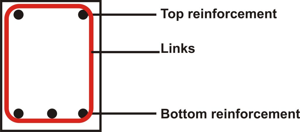
When a beam is singly reinforced, in spite that we do not need reinforcement at the top, we still nonetheless have to provide minimum area of reinforcement at the top as this reinforcement prevent undue cracking due to shrinkage and thermal stress. We also need to provide at least minimum area of reinforcement so that a reinforcement cage can be formed. These reinforcements serve as hanger bars on which shear links are tied.
You should click here to study a worked example on the design of a doubly reinforced beam to EC2
So, what’s the function of these shear links?
To properly rationalize this, we will have to understand how to design our beams against shear force.
Read also: Design of Reinfoced Concrete Beam to BS 8110-1-1997: an overview
Shear Design
Shear force is an internal force that tends to make the part of a structural member slide against another. It is often significant close to supports and under point loads. BS EN 1992-1-1: 2004 adopts the approach of variable strut inclination method for shear design; this method allows for flexibility in the angle of inclination of the compressive strut between 22 and 45.
Shear resistance of section without Shear reinforcement
Before shear reinforcement are designed, it is important that the concrete section is checked whether it has sufficient shear capacity (VRd.c) to resist the maximum design shear force (VEd) that will act on it without shear reinforcement. The shear capacity of the concrete section without shear reinforcement is often sufficient for lightly loaded beams of minor importance, however minimum area of shear reinforcement is always provided.
For member which shear reinforcement is not required, the shear capacity is given in section 6.2.2 (1) as:
VRdc = (CRdcK(100ρLfck)1/3 + K1σcp) bwd
σcp = NEd/Ac, hence where there is no axial force the equation is reduced to:
VRdc = {CRdcK(100ρLfck 1/3}bwd
From EC2 and Table NA.1 from of the UK National Annex to the code CRdc = 0.18/ϒ, hence the formular becomes:
VRdc = {0.12K(100ρLfck)1/3}bwd
This section resistance must not, however, be less than the permitted minimum resistance which is:
VRdc = {0.035K3/2fck1/2}bwd
where:
K = (1 +√200/d) ≤ 2.0
ρL = Asl/bwd ≤ 0.02
The Variable Strut Inclination Method
As for section which has the member shear capacity (VRdc) less than the design shear force (VRdc) the shear reinforcement is required and designed using the variable strut inclination method. This method is based on an imaginary truss model where concrete acts as the top chord and also acts as the diagonal strut members inclined at an angle ϴ, the bottom chords are the main tensile reinforcement while the designed links serve as the transverse tension members. The angle ϴ changes in value proportionately to the shear force acting on the member. The angle ranges between the lower and upper limit of 22 and 45 degrees respectively. It should be noted that in this imaginary truss, the contribution of the concrete to shear resistance is ignored.
Before the vertical stirrup is designed, it is important to check whether the design shear force is not too large enough to cause the crushing of the inclined compressive strut. To ensure this does not happen, the maximum resistance of the section must be greater than the design shear force.
ie: VRdmax > VEd
The formula for VRdmax is given in equation (6.9) of the code as:
VRdmax = ∝cwbwZv1cd/(cotϴ + tanϴ)
When the value of V1 in accordance with equation (6.6N) of the code and ∝cw = 1.0 are entered into the formula, it can be further simplified as:
VRdmax = (0.36bwd(1-fck/250)fck)/(cotϴ + tanϴ)
The value of ϴ to be used to check whether the section is adequate such that the compressive strut is not crushed is 45 degrees as this is the highest value of ϴ allowed by EC2 which gives the maximum resistance. When 45 is substituted for ϴ then the equation becomes:
VRdmax(45) = 0.81bwd(1 – fck/250)fck
Should VRdmax be less than VEd, the compressive strut will fail by crushing so the section is inadequate and have to be resized. However, if VRdmax is greater than VEd then we can proceed to designing the vertical links that will be required to resist the shear in the member. Different values of ϴ can be tried to achieve a shear resistance greater than the design shear force. The first value to be tried is 22 degrees as this angle gives the least resistance. If substituting 22 for ϴ does not give sufficient resistances, then a higher value of ϴ will be tried.
As an alternative and easier workaround to trying different values for ϴ until a suitable one is found, the design shear force should be equated to VRdmax so that ϴ is made the subject of the formular and a suitable value of ϴ is obtained in one swoop. Thus:
VEd = (0.36bwd(1 – fck/250)fck)/(cotϴ + tanϴ)
Once the perfect value of ϴ is obtained having modified the above equation to make ϴ the subject of the formular, this value can be plugged into the equation below: To get the shear resistance of a vertical stirrup of area Asw and spacing s, the code gives the equation to be used as:
VRd,s = (Asw/s)ZfywdCotϴ
Where; fywd = design yield strength of shear reinforcement.
The ratio of the Area and spacing of the link should not however be less than the minimum ratio as given in equation (9.5N) thus:
Asw/s = 0.08bw(√fck/fywk)
Additional Longitudinal tension reinforcement
There’s always need to provide additional longitudinal tension reinforcement at the bottom face of the section to resist the horizontal component of the force in the inclined strut. The required force to be resisted is given in equation (6.18) of EC2 which goes:
Ftd: 0.5VEd(Cotϴ – Cotα)
For all practical purpose, when curtailment length of longitudinal bars is increased beyond the position where they are not needed, then required force to counteract the longitudinal component of the force on the strut is unwittingly provided, hence separate calculation for additional longitudinal steel is often superfluous.
Deflection Check
Deflection is an important serviceability limit state that must be checked whether its limit is not exceeded. Excessive deflection can compromise the aesthetic of the structure, give impression of unsafe structure, cause damage to brittle finishes, cause problem to fixtures etc. So ensuring deflection limit is not exceeded is one of the important criteria of beam design.
The factors affecting deflection of beams are numerous likewise is calculating deflection for heterogenic material like reinforced concrete very tedious. Quasi-permanent load combination is considered for deflection; this entails considering the permanent load plus some percentage of the variable load. A fraction of the variable load is considered because the element is not expected to be exposed to the full extent of variable load consistently for long term.
The code suggests that the deflection of a beam can be estimated by calculating the curvature of the beam when un-cracked and when cracked. But a less tedious approach is to limit the span-depth ratio as this in turn limit the possible curvature of the beam. The limiting span-depth ratio can be estimated using equations below:
l/d = K[11 + 1.5√fck ρ0/ρ + 3.2√fck (ρo/ρ – 1)3/2] if ρ ≤ ρo
l/d = K[11 + 1.5√fck (ρo/ρ-ρ’) + 1/12√fck √ρ’/ρo] if ρ > ρo
The definition of the symbols in the formulas can be found under clause 7.4.2 (2) of the code.
It should also be put into consideration that the code assumes the steel stress at serviceability limit state at critical section of an element is 310MPa. This stress corresponds with yield stress of 500MPa. If other serviceability stress is used, then the equation for the limiting span-depth ratio should be modified accordingly by multiplying it by 310MPa/rows.
When the span-depth ratio of the member falls under the limiting value, it is inferred that the member has passed deflection criteria and has conformed to the code’s objective, which is to limit the deflection of the member to Span/250 or span/500 for members with brittle finishes or vulnerable adjacent part. Should the actual span-depth ratio of the member exceed the limiting span-depth ratio, the member is said to have failed deflection criteria and should therefore be redesigned.
References:
BS EN 1992-1-1: 2004 : Design of concrete structures – Part 1-1 : General rules and rules for buildings


nice post