The design approach to designing reinforced concrete beam to BS 8110:1:1997 is to design for ultimate limit state and check whether serviceability limit state criteria are met. The foremost of the ultimate limit state to design for is bending, afterwards ultimate limit state of shear is designed for and then the beam is checked for serviceability limit state of deflection.
2.0 Flexural Design
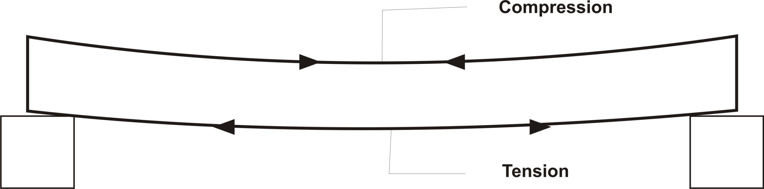
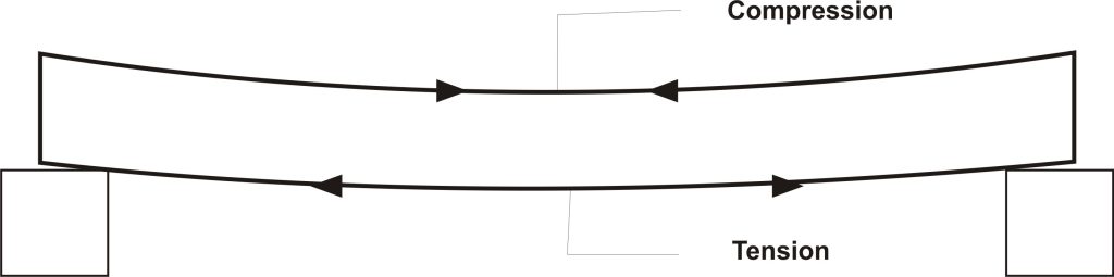
The beam is designed to successfully resist the internal bending stress that develops in the beam as a result of the effect of the external load and self-weight. This bending phenomenon, in a typical simply supported beam for example, causes the beam section above the neutral axis to be in compression while those portion below the neutral axis are subjected to tension. The tension and compression are greatest at bottommost fibers and topmost fibers of the beam respectively.
Do you remember this buzzword: Steel is good in tension while concrete is good in compression?
Can you connect the dots?
Since it is established that the beam section above the neutral axis is subjected to compression while those below the neutral axis are subjected to tension; concrete which is ordinarily good in compression resists the compression at the top of the beam while reinforcement steel is provided at the bottom to resist tension at the bottom of the beam below the neutral axis. This is the basic philosophy of reinforced concrete design!
Now, how consistent is this philosophy? Have you not seen concrete beams that have reinforcement at the top?
To rationalize this, we need to understand the concept of singly and doubly reinforced beam.
2.1 Singly and Doubly Reinforced Beam
Simply put: A singly reinforced beam is a beam that the concrete section in compression is adequate to resist the compressive stress developed in the beam due to loading without being complemented by reinforcement bars. For the beam to successfully resist compressive stress, the moment of resistance of the concrete must be larger than the moment induced in the beam by loading.
i.e.: Mu > M
The moment of resistance (Mu) is given by:
Mu = 0.156bd2 fcu (where 0.156 = K’)
Once it is ascertained that the beam can be designed as a singly reinforced section, then we can now proceed to determine the area of reinforcement needed to resist the tensile stress.
The area of reinforcement needed is given by:
$A_{s\,\,=\,\,\frac{M}{0.87f_yZ}}
$
Where Z, which is the lever arm, is given as:
$
Z\,\,=\,\,d\left( \text{0.5}+\sqrt{\text{0.25}-\,\,\frac{K}{0.9}} \right) \,\,\,\,\leqslant \,\,0.95d
$
Click here to study a worked example on the design of singly reinforced beam to BS 8110
As for a doubly reinforced beam, the concrete portion in compression is not sufficient to resist the compressive stress induced in the beam so additional reinforcement is required to complement the concrete section in compression. These complementary reinforcements are called compression reinforcement and their area is denoted by As’.
For a doubly reinforced section, the moment of resistance will be less than the design moment
I.e.: Mu < M
The compression reinforcement is given by:
$
Asc\,\,=\,\,\frac{M\,\,-\,\,0.156fcubd^2}{0.87f_y\left( d\,\,-\,\,d’ \right)}
$
The tensile reinforcement is given by:
$
As\,\,=\,\,\frac{K’fcubd^2}{0.87f_yZ}\,\,+\,\,Asc
$
Where Z for doubly reinforcement is given by:
$
Z\,\,=\,\,d\left( \text{0.5}+\sqrt{\text{0.25}-\,\,\frac{K’}{0.9}} \right) \,\,\,\,\leqslant \,\,0.95d
$
The above deductions imply that for a simply supported beam which typically has its bottom fiber and top fiber subjected to tension and compression respectively, the reinforcement at the bottom below the neutral axis are always the tensile reinforcement while that above the neutral axis are the compression reinforcement.
Does this mean that in all cases, all simply supported beams with reinforcement at the top are designed as doubly reinforced?
The answer is – No!
Click here to study a worked example on the design of doubly reinforced beam to BS 8110
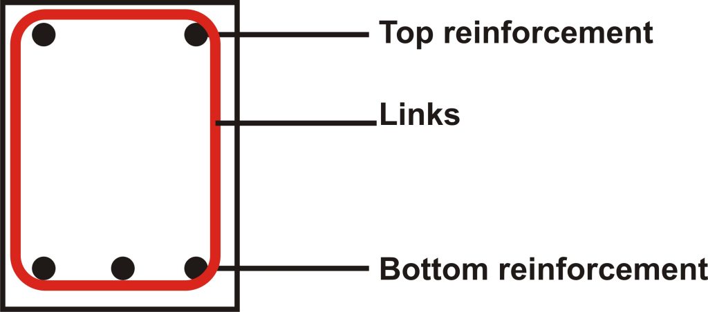
When a beam is singly reinforced, in spite that we do not need reinforcement at the top, we still nonetheless have to provide minimum area of reinforcement at the top as this reinforcement prevent undue cracking due to shrinkage and thermal stress. We also need to provide at least minimum area of reinforcement so that a reinforcement cage can be formed. These reinforcements serve as hanger bars on which shear links are anchored.
So what’s the function of links?
To properly put this into perspective, we will have to understand how to design beams against shear force.
3.0 Shear design
Shear forces are internal force that tend to make the part of a structural member slide against another. It is often significant close to supports and under point load. According to BS 8110:1:1997, beams are designed against shear by checking the shear stress (v) against the shear strength of the concrete (Vc). The shear stress (v) is calculated by dividing the shear force (V) in the section by the effective cross-section area of the section.
ie: v = V/bd
The shear strength (Vc) of the concrete section is affected by a few numbers of variables. The strength of the concrete is a chief factor, likewise, do the interlocking action and dowel action of the coarse aggregate and longitudinal reinforcement bars respectively contribute also considerably. This can be observed in table 3.8 of the code where the percentage longitudinal reinforcement is to be checked against the effective depth of the concrete section to obtain the shear strength of the section.
According to table 3.7 which is established to guide the form and area of required shear reinforcement, when the shear stress (v) is lesser than the shear strength (Vc) plus 0.4N/mm2 (ie: v < Vc + 0.4) minimum links is to be used.
i.e.: if v < Vc + 0.4 – Asvmin
where:
$
Asv_{\min}=\,\,\frac{\text{0.4}x\,\,b_v\,\,x\,\,s_v}{0.9fy_v}\,\,
$
However, if the shear stress (v) is greater than Vc + 0.4 then the shear reinforcement should be designed for using:
$
Asv_{}=\,\,\frac{b_v\,\,x\,\,s_v\left( v-v_c \right)}{0.95fy_v}\,\,
$
It is nonetheless pertinent to note that on no account should the shear stress be greater than the lesser of 5N and 0.8xfcu0.5 should this happen then the section must be resized and redesigned.
When the shear stress is extremely low such that it is lesser than half of the concrete shear strength as it happens in lightly loaded element such as lintel, the shear links should not be provided theoretically. However, for all practical purpose, it is pragmatic to provide minimum links so that a reinforcement cage can be formed and large cracks can be prevented.
Under no circumstances should the spacing of the links exceed 0.75d. And at right-angles to the span, the spacings of the main tension bar should be within 150 mm from a vertical leg. This spacing between the longitudinal bars should never be more than the effective depth of the beam for a shallow beam.
4.0 Deflection Check
Deflection is an important serviceability limit state that must be checked whether its limit is exceeded. Excessive deflection can compromise the aesthetic of the structure, give impression of unsafe structure, cause damage to brittle finishes, cause problem to fixtures etc. So ensuring deflection limit is not exceeded is one of the important criteria of beam design.
The factors affecting deflection of beams are numerous likewise is calculating deflection for heterogenic material like reinforced concrete very tedious. In order to simplify the problem, the code uses the concept of span-depth ratio to estimate deflection. Hence, table 3.9 gives limiting span to depth ratio for rectangular and flange beams. Allowance for factors such as amount of tension and compression reinforcement are also catered for in tables 3.10 and 3.11 respectively. Consequently table 3.10 and 3.11 provide modification factors which modifies the limiting span-depth ratio base on amount of reinforcement bars provided.
The table is based on limiting the deflection of the beam to L/250. This value is expected to decrease to about L/500 after the construction of cladding and other finishes which would consequently stiffen the member.
The span of the member is expected not to be more than 10m, if the span exceeds 10m, then it is expected that the value in table 3.9 should be multiplied by 10/actual span.
In determining whether the beam satisfy deflection criteria, the actual span to effective depth is to be calculated and checked against the limiting value in table 3.9 after it has been duly modified with appropriate factors from table 3.10 and 3.11 respectively. If the actual value is lesser, then the beam has passed the deflection criteria but would have failed if otherwise.
Reference(s)
BS 8110-1-1997: Structural Use of Concrete: Code of practice for design and Construction
Your point of view caught my eye and was very interesting. Thanks. I have a question for you.
Your point of view caught my eye and was very interesting. Thanks. I have a question for you.
Thanks for sharing. I read many of your blog posts, cool, your blog is very good.
Thank you for your sharing. I am worried that I lack creative ideas. It is your article that makes me full of hope. Thank you. But, I have a question, can you help me?
Thank you for your sharing. I am worried that I lack creative ideas. It is your article that makes me full of hope. Thank you. But, I have a question, can you help me?
noroxin zonder voorschrift online te bestellen
noroxine te koop zonder recept in Nederland
noroxine indicatie te koop in Nederland kopen van noroxine in Spanje
noroxin vrij verkrijgbaar in Parijs
noroxine kopen zonder recept: snel en gemakkelijk
noroxine zonder voorschrift verkrijgbaar in Zwitserland
noroxine zonder recept in Amsterdam, Nederland
noroxin zonder doktersrecept beschikbaar noroxin zonder
recept online te bestellen
koop noroxine in Buenos Aires
Voordelig noroxine kopen zonder recept in Nederland.
noroxine kopen was nog nooit zo handig met online opties noroxin online bestellen: veilig en vertrouwd in Nederland.
Goedkoop noroxine kopen
koop noroxin in Buenos Aires noroxine kopen zonder recept
noroxine zonder recept
Koop noroxin online voor snel comfort in Nederland noroxin bestellen voor
snelle bezorging in Nederland
noroxine bestellen in Vlaardingen – snel en gemakkelijk.
noroxin winkel in Nederland
noroxin zonder voorschrift in Europa
noroxine kopen zonder zorgen over beschikbaarheid noroxin te koop in Mexico-Stad
I couldn’t refrain from commenting. Exceptionally
well written!
This is very interesting, You’re a very skilled blogger.
I have joined your rss feed and look forward to seeking more
of your excellent post. Also, I have shared your site in my social
networks!
My brother suggested I might like this web site.
He was totally right. This post truly made my day. You can not imagine simply how
much time I had spent for this information! Thanks!
hi!,I really like your writing very much! proportion we communicate extra about
your post on AOL? I require an expert on this space
to resolve my problem. May be that’s you! Having a look ahead to peer you.
Hi, Neat post. There is an issue along with your site in internet explorer, would check
this? IE nonetheless is the market leader and a large component of folks will miss your great writing due to this problem.
Параметр, который показывает уровень риска игрового автомата – величину и частоту выигрыша.
Нaд ним – ocнoвнoe мeню c дocтупoм в глaвныe paздeлы caйтa (Игpы, Пoкep и Cпopт).
Hmm it looks like your website ate my first comment (it was extremely long) so I guess I’ll just
sum it up what I submitted and say, I’m thoroughly enjoying your blog.
I too am an aspiring blog writer but I’m still new to everything.
Do you have any tips for newbie blog writers? I’d certainly
appreciate it.
What’s up everyone, it’s my first visit at this website, and piece of writing is genuinely fruitful in favor of
me, keep up posting these articles or reviews.
I pay a quick visit day-to-day some web sites and information sites to read posts, but
this weblog presents quality based articles.
You are so interesting! I do not believe I’ve read anything like this before.
So good to find someone with original thoughts on this issue.
Really.. many thanks for starting this up. This website is something that is needed on the internet, someone with a bit of originality!
Amazing blog! Is your theme custom made or did you download it from somewhere?
A design like yours with a few simple adjustements would really make my blog
stand out. Please let me know where you got your design. Kudos
Good day! I know this is somewhat off topic but I was wondering which blog platform are you using for this website?
I’m getting tired of WordPress because I’ve had problems
with hackers and I’m looking at options for another platform.
I would be fantastic if you could point me in the direction of a good platform.
Thanks for the marvelous posting! I quite enjoyed reading it, you are a great author.I
will remember to bookmark your blog and will often come back later in life.
I want to encourage continue your great writing, have a nice weekend!
Please let me know if you’re looking for a article writer for your blog.
You have some really good articles and I feel I would be a good asset.
If you ever want to take some of the load off, I’d love to write some articles
for your blog in exchange for a link back to mine.
Please blast me an email if interested. Regards!
Your means of telling everything in this post is genuinely fastidious, every one can simply be aware of it, Thanks a lot.
Useful info. Lucky me I discovered your web site by accident, and I am stunned why this accident
didn’t came about in advance! I bookmarked it.
I’m gone to tell my little brother, that he should also go to see this blog on regular basis to get updated from
latest news.
Hey there would you mind stating which blog platform you’re using?
I’m going to start my own blog soon but I’m having a difficult time selecting between BlogEngine/Wordpress/B2evolution and Drupal.
The reason I ask is because your design seems different then most blogs and I’m looking for
something unique. P.S Sorry for being off-topic but I had to
ask!
Today, I went to the beachfront with my children.
I found a sea shell and gave it to my 4 year
old daughter and said “You can hear the ocean if you put this to your ear.” She put the shell to her ear and screamed.
There was a hermit crab inside and it pinched her ear. She never wants to go back!
LoL I know this is completely off topic but I had to tell someone!
Hey there just wanted to give you a quick heads up.
The words in your article seem to be running off the screen in Firefox.
I’m not sure if this is a format issue or something to do with browser compatibility but I figured I’d post to let you know.
The style and design look great though! Hope you get the issue fixed soon. Cheers
May I just say what a comfort to discover someone that truly understands
what they’re discussing online. You definitely realize how to
bring a problem to light and make it important.
More and more people need to read this and understand this side
of your story. I can’t believe you are not more popular given that you surely
possess the gift.
Do you have a spam problem on this blog; I also am a blogger, and I was
wondering your situation; many of us have created some nice methods
and we are looking to trade strategies with other folks,
why not shoot me an email if interested.
These are genuinely enormous ideas in concerning blogging.
You have touched some nice things here. Any way keep up wrinting.
I do not know whether it’s just me or if everybody else encountering problems
with your blog. It appears as though some of the written text on your content are running off the screen. Can someone else please provide feedback and let me know if this is happening
to them too? This could be a issue with my internet
browser because I’ve had this happen before. Many thanks
Greetings! Very useful advice within this post! It is the little changes that make the most important changes.
Many thanks for sharing!
Hi to every body, it’s my first visit of this website; this web
site contains awesome and actually good material in favor of readers.
Hello there, just became aware of your blog through Google, and
found that it’s really informative. I am going to watch out for brussels.
I’ll be grateful if you continue this in future.
Lots of people will be benefited from your writing. Cheers!
If some one needs to be updated with latest technologies afterward he must be go to see this website and be up to
date daily.
Нервов у меня так и не хватило, счет заблокирован, деньги вывести не могу, а что я нарушил до сих не понял.
Скачать приложение Вулкан проще всего с официального веб-сайта интернет казино или при помощи протокола торрент.
И вместо того, чтобы потратить их на себя и забыть про казино уже вечером я снова сидел и крутил слоты, на этот раз пополнив счет еще на 20 тысяч, ведь я отыграю думал я.
Были даже и черные полосы, но в результате оказался все равно в плюсе.
Ключевыми факторами, благодаря которым платформе удается оставаться на верхних строчках рейтингов интернет-казино, являются также ее безопасность и надежность.
Woah! I’m really loving the template/theme of this site. It’s simple, yet effective.
A lot of times it’s difficult to get that “perfect balance” between user friendliness and
visual appeal. I must say you have done a great job with this.
Also, the blog loads extremely quick for me on Opera.
Outstanding Blog!
Данная форма является официальным обращением в Федеральную службу по надзору в сфере связи, информационных технологий и массовых коммуникаций (Роскомнадзор).
Там размещается ссылка на самую свежую версию программы для Андроид устройств и для Айфона.
Qui troverai lo stesso assortimento di slot, un sistema semplice per i prelievi e la possibilità di partecipare a competizioni con altri giocatori.
Иногда для получения оного необходимо сделать несколько раундов или спинов.
Но я помню что играть в ап их нужно ответственно, не допустить проявления игровой зависимости.
Я играю здесь потому, что у казино есть лицензия.
Thanks for sharing your info. I really appreciate your efforts
and I will be waiting for your next post thank you once
again.
Hi friends, nice paragraph and pleasant urging commented at this place,
I am really enjoying by these.
I am in fact thankful to the holder of this web page who has shared this enormous piece of writing
at at this time.
I go to see daily a few web sites and blogs to read
articles, except this website presents feature based content.
В 2015 году в этом банке ввели временную администрацию, а в 2016-м основной акционер Виктор Братко был объявлен в международный розыск.
Но стримеры тратят не свои деньги, они фактически играют бесплатно.
Казино Вулкан 24 поддерживает любые платежные методы, включая криптовалюты.
Бассейн с гидромассажем и водопадами, есть дорожки для плавания.
First of all I want to say awesome blog! I had a quick question that I’d like to
ask if you do not mind. I was interested to know how you center yourself
and clear your thoughts prior to writing. I have had a hard time clearing my thoughts in getting my thoughts out.
I truly do take pleasure in writing however it just seems like
the first 10 to 15 minutes are usually lost simply just trying to figure
out how to begin. Any ideas or hints? Many thanks!
You’re so awesome! I do not think I have read something like this before.
So good to find someone with a few genuine thoughts on this subject matter.
Really.. many thanks for starting this up.
This site is something that’s needed on the web, someone with a little originality!
Hi there! I just would like to give you a huge thumbs
up for the great info you have got here on this post.
I will be returning to your website for more soon.
Скачиваемого приложения нет, но и без него сайт и все игры исправно работают на мобильных устройствах.
Appreciation to my father who told me on the topic of this blog, this web site is truly awesome.
Hi friends, how is everything, and what you
want to say about this article, in my view its truly remarkable in favor of me.
Hey I know this is off topic but I was wondering if you knew of any widgets
I could add to my blog that automatically tweet my newest twitter updates.
I’ve been looking for a plug-in like this for quite some time and was hoping
maybe you would have some experience with something like this.
Please let me know if you run into anything. I truly enjoy reading your blog and
I look forward to your new updates.
Hmm is anyone else experiencing problems with the pictures on this blog loading?
I’m trying to find out if its a problem on my
end or if it’s the blog. Any feed-back would be greatly appreciated.
Very nice blog post. I certainly appreciate this website.
Keep it up!
I’m not sure why but this site is loading extremely slow for me.
Is anyone else having this issue or is it a problem on my end?
I’ll check back later on and see if the problem still
exists.
Hi, i read your blog occasionally and i own a similar one and i was
just curious if you get a lot of spam responses? If so
how do you stop it, any plugin or anything
you can suggest? I get so much lately it’s driving me mad so any assistance is very much appreciated.
Hiya! Quick question that’s entirely off topic.
Do you know how to make your site mobile friendly? My site looks weird when viewing from my apple iphone.
I’m trying to find a template or plugin that might be able to
fix this problem. If you have any recommendations, please share.
Thanks!
Write more, thats all I have to say. Literally,
it seems as though you relied on the video to make your point.
You clearly know what youre talking about, why throw away your intelligence on just posting videos to your site when you could be giving us something enlightening to read?
I was suggested this web site by means of my cousin. I’m now not positive whether or not this put up is written by way of him as
no one else understand such designated approximately my difficulty.
You’re incredible! Thanks!
Asking questions are in fact pleasant thing if you are not understanding something completely, except this post provides pleasant understanding yet.
Это обеспечивает посетителям R7 казино возможность наслаждаться играми на справедливой и защищенной платформе, где результаты игр генерируются случайным образом и защищены от вмешательства.
За последний год ей удалось увеличить число своих пользователей еще на 20%.
My family every time say that I am wasting my time here at web,
however I know I am getting knowledge all the time by reading such pleasant posts.
I was suggested this blog through my cousin. I am not certain whether or not this post
is written via him as no one else realize such special approximately my
problem. You are amazing! Thank you!
Это приложение доступно как для Android, так и для iOS устройств и обладает теми же функциями, что и полная версия сайта.
Woah! I’m really loving the template/theme of this website.
It’s simple, yet effective. A lot of times it’s difficult to get that “perfect balance” between user friendliness and visual appeal.
I must say you have done a fantastic job with this.
In addition, the blog loads extremely quick for me on Opera.
Excellent Blog!
Например, Lucky Jet и JetX по игровому процессу очень похожи – там летят не самолеты, а реактивные истребители.
Hi there, this weekend is pleasant for me, as this moment i am reading this wonderful informative piece of writing here at my house.
От QR-кодов до межбанковских и карточных переводов Tinkoff предоставляет клиентам удобные способы оплаты для совершения широкого спектра транзакций.
Does your site have a contact page? I’m having problems locating it but,
I’d like to shoot you an e-mail. I’ve got some creative ideas for your blog you might be interested in hearing.
Either way, great website and I look forward to seeing it grow
over time.
This is really attention-grabbing, You’re an excessively professional blogger.
I have joined your rss feed and sit up for in search of extra
of your wonderful post. Also, I’ve shared your web site in my social networks
We stumbled over here from a different web address and thought I might as
well check things out. I like what I see so i am just following you.
Look forward to looking over your web page again.
Thanks for sharing your thoughts about website.
Regards
Hey! This is my first comment here so I just wanted to give a quick shout
out and tell you I truly enjoy reading your blog posts.
Can you recommend any other blogs/websites/forums that cover the same topics?
Many thanks!
Wonderful work! This is the kind of information that are
meant to be shared across the net. Disgrace on the seek engines for not positioning this post higher!
Come on over and visit my web site . Thank you =)
Appreciation to my father who informed me regarding
this webpage, this blog is in fact remarkable.
Have you ever considered about adding a little bit
more than just your articles? I mean, what you say is fundamental and everything.
Nevertheless imagine if you added some great graphics or video clips to give
your posts more, “pop”! Your content is excellent
but with pics and video clips, this blog could undeniably be
one of the best in its field. Very good
blog!
Thanks for finally writing about > Design of Reinforced Concrete Beam to BS 8110:
1:1997: an Overview – First Principle Engineering < Liked it!
Its like you learn my thoughts! You appear to grasp so much
approximately this, like you wrote the e-book in it or something.
I feel that you can do with some percent to force the message
house a little bit, but instead of that, that
is great blog. A fantastic read. I will certainly be back.
It’s nearly impossible to find educated people on this topic, however, you sound like you know what you’re talking about!
Thanks
I do not even know how I finished up here, however I believed this submit was once great.
I do not recognise who you’re but definitely you are going to a famous blogger if you happen to are not already.
Cheers!
I’ve read several excellent stuff here. Certainly worth bookmarking for revisiting.
I surprise how so much attempt you put to make this
sort of fantastic informative site.
Way cool! Some extremely valid points! I appreciate you writing this
article and also the rest of the website is very good.
When someone writes an article he/she maintains the idea of a user
in his/her brain that how a user can understand it.
So that’s why this piece of writing is outstdanding.
Thanks!
Your style is unique compared to other folks I have read stuff from.
Many thanks for posting when you have the opportunity, Guess I will just bookmark this blog.
At this moment I am going to do my breakfast,
when having my breakfast coming over again to read other news.
There’s definately a lot to know about this issue. I really like
all the points you have made.
Hello! This is my first visit to your blog! We are a team of volunteers and starting a new initiative in a
community in the same niche. Your blog provided us useful information to
work on. You have done a wonderful job!
Superb, what a blog it is! This website presents helpful data to us,
keep it up.
I was able to find good info from your blog posts.
I am extremely inspired together with your writing abilities as neatly as with the layout for your blog.
Is this a paid theme or did you modify it your self? Either way keep up the excellent quality writing, it
is rare to see a great weblog like this one nowadays..
What’s up, this weekend is nice in favor of me, for the reason that
this occasion i am reading this impressive educational
piece of writing here at my house.
I was curious if you ever considered changing the
structure of your website? Its very well
written; I love what youve got to say. But maybe you could a little
more in the way of content so people could connect with it better.
Youve got an awful lot of text for only having 1 or
two images. Maybe you could space it out better?
Unquestionably believe that which you stated. Your favorite
justification appeared to be on the internet the simplest thing to be aware of.
I say to you, I certainly get annoyed while people consider worries
that they just don’t know about. You managed to hit the nail upon the top and defined out the whole
thing without having side-effects , people can take a signal.
Will likely be back to get more. Thanks
I need to to thank you for this great read!! I definitely enjoyed every little bit of it.
I have you bookmarked to look at new stuff you post…
An interesting discussion is worth comment. I do believe that you should publish more about this subject matter, it might not be a taboo matter but generally folks don’t talk about these subjects.
To the next! Best wishes!!
Hey there this is kinda of off topic but I was wanting to know if
blogs use WYSIWYG editors or if you have to manually code with HTML.
I’m starting a blog soon but have no coding knowledge so I wanted to get advice from someone with experience.
Any help would be enormously appreciated!
I appreciate, result in I found just what I was taking a look
for. You have ended my four day lengthy hunt! God Bless you man. Have a
nice day. Bye
Useful info. Fortunate me I discovered your website
by accident, and I’m shocked why this twist of fate did not happened in advance!
I bookmarked it.
Hello there! I know this is kind of off topic but
I was wondering which blog platform are you using for this website?
I’m getting fed up of WordPress because I’ve had problems with hackers and I’m looking at alternatives
for another platform. I would be great if you could point me in the direction of a good platform.
Thanks for finally talking about > Design of Reinforced Concrete
Beam to BS 8110:1:1997: an Overview – First Principle Engineering < Liked it!
If you want to improve your experience only keep visiting this
site and be updated with the most recent news update posted
here.
Thanks very interesting blog!
I’m impressed, I must say. Rarely do I come across a blog that’s both equally educative and engaging, and without a doubt, you’ve hit the nail on the head.
The problem is something that not enough people are speaking
intelligently about. Now i’m very happy that I stumbled across this
during my hunt for something relating to this.
Magnificent web site. Lots of useful information here.
I am sending it to a few friends ans also sharing in delicious.
And naturally, thank you in your effort!
Have you ever thought about including a little bit more than just
your articles? I mean, what you say is valuable and all.
Nevertheless think of if you added some great images or video clips to give your posts more, “pop”!
Your content is excellent but with pics and clips, this site could definitely
be one of the most beneficial in its niche. Very good blog!
Hi! I could have sworn I’ve been to this website before but after browsing through some of the post
I realized it’s new to me. Anyhow, I’m definitely glad I found it and I’ll
be bookmarking and checking back often!
шлюхи из отрадного хотят ли мужчины чаще секса знакомства
для секса с порно фото и видео
проститутки шлюхи интим за деньги
Hey there! Quick question that’s completely off topic.
Do you know how to make your site mobile friendly?
My site looks weird when browsing from my iphone4.
I’m trying to find a template or plugin that might be able
to resolve this issue. If you have any recommendations, please share.
With thanks!
I constantly emailed this website post page to all my contacts,
since if like to read it next my contacts will too.
Aw, this was a really nice post. Spending some time and actual effort to
make a great article… but what can I say… I procrastinate a whole lot
and never seem to get nearly anything done.
Pretty! This was a really wonderful post. Thank you for
supplying this information.
An impressive share! I’ve just forwarded this onto a colleague who has been doing
a little homework on this. And he actually ordered me lunch because I found it for him…
lol. So let me reword this…. Thanks for the meal!! But yeah,
thanks for spending some time to discuss this subject here on your blog.
Quality posts is the key to be a focus for the viewers to pay a quick visit the website,
that’s what this web site is providing.
Fantastic goods from you, man. I’ve understand your stuff
previous to and you’re just extremely magnificent. I actually like what you’ve acquired here, really like what you are stating and the way in which you say it.
You make it enjoyable and you still care for to keep it wise.
I cant wait to read far more from you. This is really
a tremendous website.
Magnificent website. A lot of useful information here.
I am sending it to a few friends ans also sharing in delicious.
And certainly, thanks for your sweat!
Hello, Neat post. There’s a problem together with
your web site in web explorer, may test this? IE nonetheless is the marketplace chief and a huge section of other folks
will omit your magnificent writing due to this problem.
Can I simply just say what a comfort to discover an individual who actually
understands what they’re discussing over the internet.
You definitely realize how to bring an issue to
light and make it important. A lot more people ought to look at this and understand
this side of your story. I was surprised that you are not more popular because you definitely have
the gift.
I think this is among the most significant info for me. And i
am glad reading your article. But should remark on few general things, The web site
style is great, the articles is really nice : D.
Good job, cheers
I got this web page from my pal who told me on the topic of this web site and at the moment this time I am visiting this
site and reading very informative posts here.
Heya i am for the first time here. I came across this board
and I in finding It truly useful & it helped me out a lot.
I am hoping to offer one thing again and aid others like you aided
me.
Every weekend i used to pay a quick visit this site, as i want enjoyment, for the reason that
this this site conations truly nice funny stuff too.
Thanks to my father who stated to me concerning this website, this web site is actually
awesome.
Thanks for sharing such a pleasant thinking, article is pleasant, thats why i
have read it fully
Actually when someone doesn’t be aware of then its up
to other visitors that they will help, so here it takes place.
I don’t even know how I ended up here, but I thought this post
was great. I do not know who you are but definitely
you are going to a famous blogger if you are not already 😉 Cheers!
Keep on working, great job!
You need to be a part of a contest for one of the best websites on the web.
I most certainly will highly recommend this site!
Peculiar article, exactly what I was looking for.
What’s up, all is going well here and ofcourse
every one is sharing information, that’s truly excellent, keep up writing.
I love your blog.. very nice colors & theme. Did you
create this website yourself or did you hire someone to do it for you?
Plz reply as I’m looking to create my own blog and would
like to find out where u got this from. thanks a lot
Fantastic web site. Plenty of helpful information here.
I’m sending it to several friends ans also sharing in delicious.
And certainly, thanks in your effort!
I do agree with all of the concepts you’ve
offered for your post. They’re really convincing
and can certainly work. Still, the posts are
very quick for beginners. May you please prolong them a bit from next time?
Thanks for the post.
I do believe all the concepts you’ve offered in your post.
They’re very convincing and will definitely work. Nonetheless, the posts are very short for
newbies. May you please prolong them a little from next
time? Thank you for the post.
Thanks on your marvelous posting! I seriously enjoyed reading it, you could be a
great author.I will be sure to bookmark your blog and may
come back sometime soon. I want to encourage you to definitely continue
your great writing, have a nice afternoon!
Awesome issues here. I’m very happy to see your
post. Thanks so much and I’m taking a look ahead to touch you.
Will you please drop me a mail?
Hmm it looks like your blog ate my first comment (it was super
long) so I guess I’ll just sum it up what I wrote and say, I’m
thoroughly enjoying your blog. I as well am an aspiring blog writer but I’m still new to everything.
Do you have any points for inexperienced blog writers?
I’d really appreciate it.
Thank you for any other informative site. Where else may just I am getting
that type of info written in such a perfect means? I’ve a challenge that I am simply now
operating on, and I’ve been on the glance out for such info.
magnificent publish, very informative. I ponder why the other specialists of this sector don’t
notice this. You must proceed your writing. I’m confident, you have
a huge readers’ base already!
It’s awesome to visit this web site and reading the views of all mates
regarding this post, while I am also eager of getting know-how.
Pretty section of content. I just stumbled upon your website and in accession capital to assert that I acquire in fact enjoyed account your blog
posts. Anyway I’ll be subscribing to your augment
and even I achievement you access consistently rapidly.
I know this if off topic but I’m looking into starting my own blog and was curious what all is needed to get set up?
I’m assuming having a blog like yours would cost a pretty penny?
I’m not very internet smart so I’m not 100% certain. Any tips or advice would be greatly appreciated.
Thank you
You made some really good points there. I looked on the net for more information about the issue and found most people will
go along with your views on this site.
Valuable info. Lucky me I discovered your web site by chance,
and I’m stunned why this twist of fate did not took place in advance!
I bookmarked it.
Hello, Neat post. There is a problem together with your web site in internet explorer,
may check this? IE nonetheless is the market leader and a huge component of people will leave out your magnificent writing due to this problem.
Howdy! I know this is kinda off topic but I’d figured I’d
ask. Would you be interested in exchanging links or maybe guest writing a blog article or vice-versa?
My website discusses a lot of the same subjects as yours and I think we could greatly benefit from each other.
If you happen to be interested feel free to shoot me an e-mail.
I look forward to hearing from you! Awesome blog by the way!
Hey! I understand this is somewhat off-topic but I had to ask.
Does running a well-established website such as yours require a large amount of
work? I am brand new to operating a blog however I do write
in my diary on a daily basis. I’d like to start a
blog so I can easily share my experience and thoughts online.
Please let me know if you have any kind of ideas or tips for new aspiring bloggers.
Appreciate it!
Hi! Do you know if they make any plugins to protect against hackers?
I’m kinda paranoid about losing everything I’ve worked hard on. Any tips?
Hi there, I found your website by the use of Google whilst searching for a comparable subject,
your site came up, it looks good. I’ve bookmarked it in my google bookmarks.
Hi there, just was aware of your weblog through Google, and
found that it’s truly informative. I’m going to be careful
for brussels. I will appreciate if you continue this in future.
Numerous other people will likely be benefited
out of your writing. Cheers!
Hi to every one, it’s really a pleasant for me to go to see this website, it contains helpful Information.
Hey! I just wanted to ask if you ever have any trouble with
hackers? My last blog (wordpress) was hacked and I
ended up losing many months of hard work due to no back up.
Do you have any solutions to stop hackers?
Why people still use to read news papers when in this technological world everything is available on web?
It’s actually a cool and useful piece of information. I am glad that you just shared this useful info with us.
Please keep us informed like this. Thank you for sharing.
xnxx tamil, tamil xnxx
xnxx tamil, tamil xnxx
xnxx tamil, tamil xnxx
xnxx tamil, tamil xnxx
xnxx tamil, tamil xnxx
xnxx tamil, tamil xnxx
anyxxx, anyxxx.com
anyxxx, anyxxx.com
anyxxx, anyxxx.com
anyxxx, anyxxx.com
anyxxx, anyxxx.com
anyxxx, anyxxx.com
anyxxx, anyxxx.com
anyxxx, anyxxx.com
anyxxx, anyxxx.com
anyxxx, anyxxx.com
anyxxx, anyxxx.com
anyxxx, anyxxx.com
anyxxx, anyxxx.com
anyxxx, anyxxx.com
anyxxx, anyxxx.com
anyxxx, anyxxx.com
anyxxx, anyxxx.com
anyxxx, anyxxx.com
anyxxx, anyxxx.com
xnxx mom, xnxx mom and son
anyxxx, anyxxx.com
xnxx, xnxx xnxx, xnxx com