Slabs are floor system which are mostly the first and direct load bearing member in many structures. These loads on slabs are often uniformly distributed and act normally to the plane of the slab. Loads on slab have to be transferred to supporting beams and then to columns before it goes down to the foundation.
There are several ways of distributing slab loads to beams; these methods vary in their degree of accuracy and conservativeness. However, since the advent of Finite Element Analysis software, distributing slab loads using FEA has become popular. This is even highly recommended when the slab is of irregular shape or supporting a direct point load.
Before diving into using FEA software for complex analysis, it is incumbent on an engineer to understand the basics of load distribution so that he can understand and better interprets or modify results obtainable from his software. There is no other better way to introduce one to load distribution from slab other than using Yield line method which is easily executable by hand calculation.
In using Yield line method, the shape and dimension of each slab informs the yield line pattern which consequently defines the tributary area for the supporting beams.
2.0 Tributary Area
The tributary area is the area portion of load of a slab that will be supported by a beam or column. These tributary areas are defined by drawing the yield line pattern of the slab. And this is dependent on the slab’s dimension, and the arrangement of its supports.
2.1 Tributary Area of One-way slabs
A one-way slab is a slab which is either supported only on two parallel sides or a slab which has the ratio of the longer span (ly) to the shorter span (lx) to be greater than 2.
mathematically: ly/lx > 2
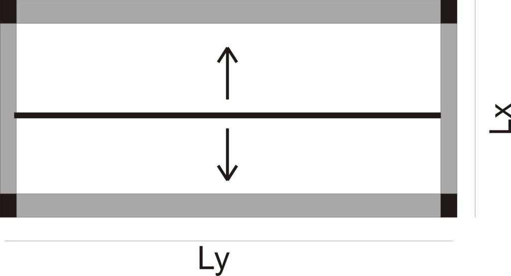
For such a slab, the yield line pattern is drawn in the middle of the slab parallel to the longer sides. This makes the tributary areas to be two equal rectangles which share equal amount of slab load to the two supporting beams.
2.1.1 Slab loads supported by beam.
In a one-way slab, the slab load supported by a beam is obtained by multiplying the tributary area of the beam by the slab loads.
mathematically: Ar x ꟺ
Where: Ar is the area of the rectangular tributary area
ꟺ is the load on the slab.
2.2 Tributary Area of Two-Way Slabs
A two-way slab is a slab that has the ratio of the longer side (Ly) to the shorter side (Lx) to be less than or equal to 2.
mathematically: Ly/Lx ≤ 2
The yield line pattern for a two-way slab depends on whether the slab geometry is a rectangle or a square. If the geometry is a rectangle, the yield line pattern forms two trapezoidal shapes and two triangular shapes as shown in fig (2). The trapezoidal shapes serve as the tributary area for the longer beams while the triangular shapes become the tributary area for the shorter beams.
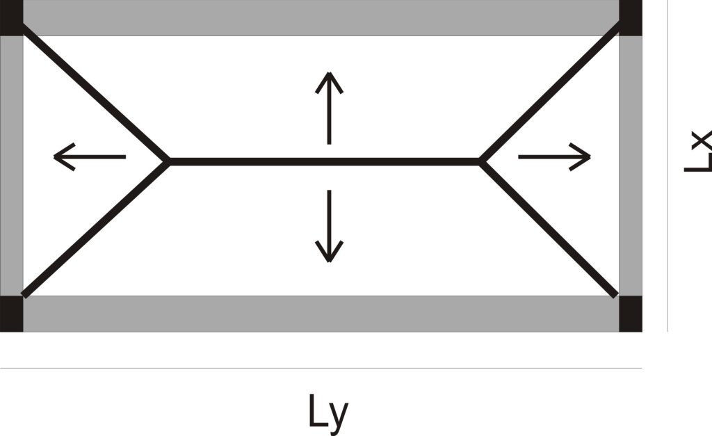
fig (2)
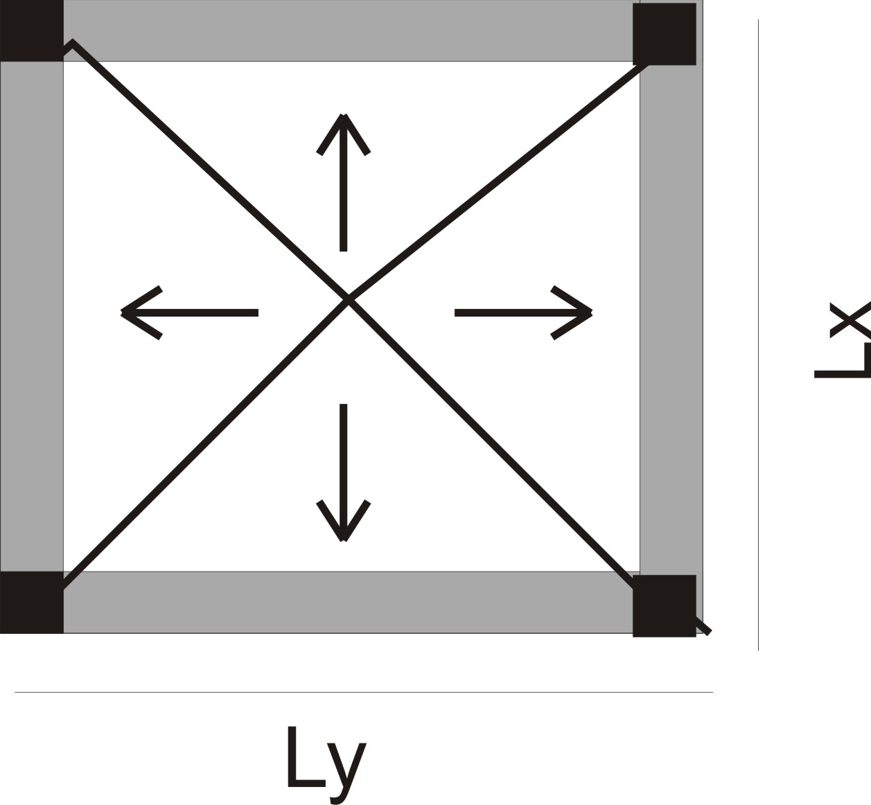
However, if the slab is square, the yield line patterns form four triangles of equal dimensions (see fig (3)). This implies loads are shared equally to all supporting beams.

fig (3)
2.2.2 Slab loads supported by beam.
For a two-way slab, the load on a beam is equal to the tributary area for the beam multiplied by the slab load. The tributary area can either be a triangle or a trapezium.
mathematically: Ar x ꟺ or At x ꟺ
Where:
Ar is the area of the rectangle
At represents the area of the trapezium
3.0 Worked Example: Distribution of slab load to beams.
Fig shows a floor plan, use the data below to estimate the slab loads transferred to Beam 1, Beam 2, and Beam 3.
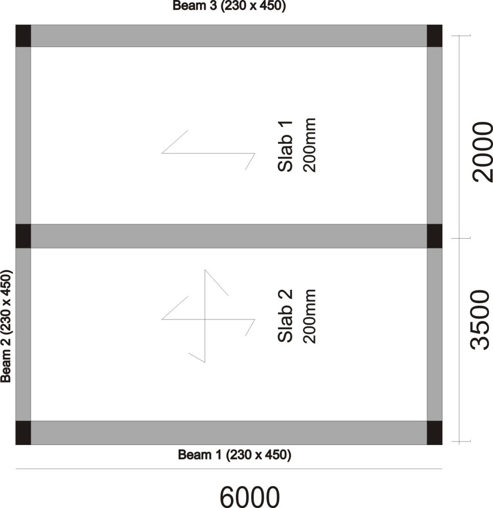
fig (4)
Data:
Live Load on slab = 1.5KN/m2
Finishes = 1.0KN/m2
Unit weight of concrete = 24KN/m2
Thickness of Slab = 200mm
Fig (5) shows the yield line pattern of the slab. The arrows indicate how the slab loads are distributed to respective beams.
")
fig (5)
BEAM 3
Beam 3 is supporting a one-way span slab which makes it to receive half of the loads on the slab. The loads from the slab can be estimated as follows.
Dead Load
Characteristic Self-weight of slab = 0.2 x 24 = 4.8KN/m2
(NB: The self-weight of slab is obtained by multiplying the slab thickness by the unit weight of the concrete as shown below)
Finishes Load on Slab = 1.0KN/m2
Characteristic Dead Load on Slab = 4.8 + 1.0 = 5.8KN/m2
(NB: The dead load of the slab is obtained by adding up the self-weight of the slab and the partition load.)
Live Load
Live load on slab = 1.5KN/m2
Ultimate Load on the slab
We will obtain the ultimate slab load by multiplying the live load by 1.4 and the dead load by 1.6.
Ultimate Load acting on Slab = 1.4(5.8) + 1.6(1.5) = 10.52KN/m2
Tributary area
(We will now calculate the area of load from the slab that will be supported by beam 3. Since the slab supported by beam 3 is one-way, the area of load that will be supported by the beam is half of the area the slab it is supporting. This area forms a rectangle as delineated by the yield line in fig (5)).
Area of Slab load Supported by Beam 3 = 6 x 2/2 = 6m2
(The area of load is as shown above. However, it is ideal that the load on a beam is left as a line load which is per meter length. So, in order to maintain this, we will divide the area by the length of the beam which is 6m.)
Modified Area of Slab load Supported by Beam 3 = 6/6 = 1m
The total load from slab supported by Beam 3 = 1 x 10.52 = 10.52KN/m
This means the beam supports a line load of 10.52KN per each meter.
BEAM 1
Beam 1 is supporting a two-way span slab on the longer side which makes it to receive a portion of the slab load which tributary area is trapezoidal. The loads on the slab are as previously estimated for beam 3 as the thickness of the slab is uniform. Hence the factored load is reproduced below:
Factored Loads
Ultimate Load acting on Slab =1.4(5.8) + 1.6(1.5) = 10.52KN/m2
Tributary area
From basic mathematics, the area of a trapezium = 0.5 x (a + b) h
The variables in the formula are related to the trapezium as shown in the figure below.
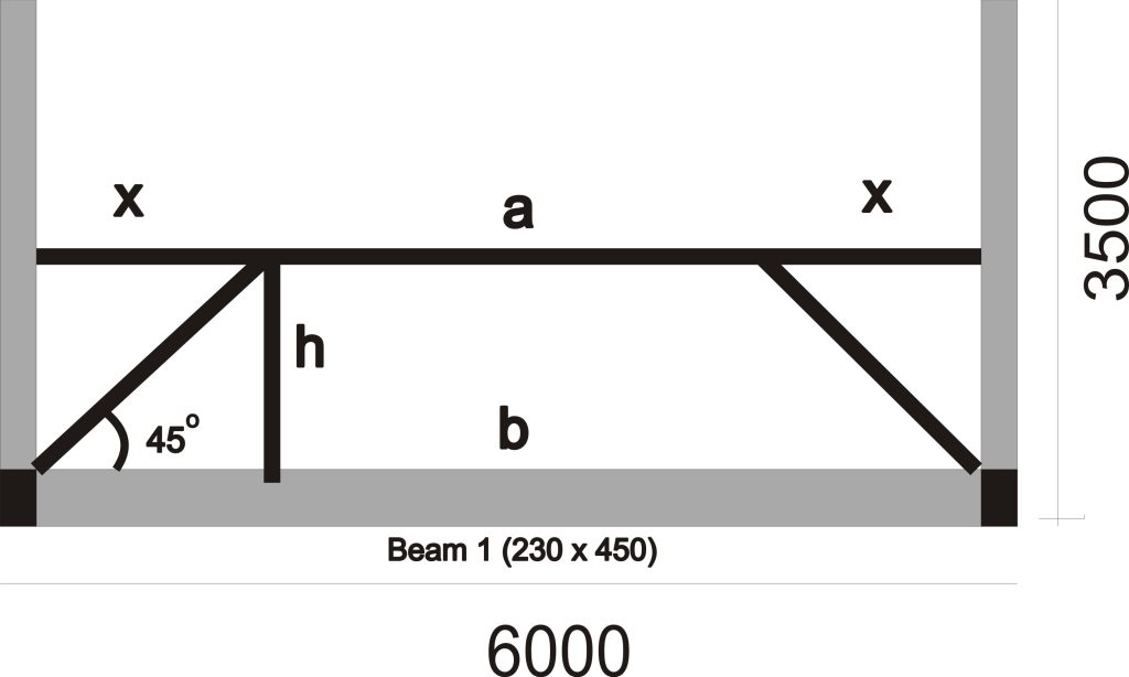
b = 6m
h = 3.5/2 = 1.75 (This is gotten by dividing the shorter length of the slab by 2)
a = 6 – 2x
The value of x can be obtained using trigonometry ratio.
tanϴ = Opp/Adj
ϴ = 450 (This is the assumed angle of dispersion of slab load from years of empirical evidence)
tan450 = h/x
x = 1.75/1
x = 1.75
a = 6 – 2 x 1.75
a = 2.5m
Area of Slab load Supported by Beam 1 = (0.5 x 6 x 2/2)/ 6 = 1.24m2
(Remember, the area of the trapezium is divided by the length of the beam which is 6m so that the loads on the beam can be maintained as line load which is per meter run (m-1)
The total load from slab supported by Beam 1 = 1.24 x 10.52 = 13.0KN/m
BEAM 2
Beam 2 is supporting a two-way span slab on the shorter side which makes it to receive a triangular area of slab loads. The loads on the slab are as previously estimated as the thickness of the slab is constant throughout. Hence the factored load is reproduced below:
Factored Loads
Ultimate Load acting on Slab =1.4(5.8) + 1.6(1.5) = 10.52KN/m2
Tributary area
(The tributary area is a triangle. However, we will divide the tributary area by the length of the beam so as to keep the slab loads on the beam in per meter (m-1)
Area of Slab load Supported by Beam 2 = 0.5 x 3.5 x 1.75 /3.5 = 0.875
The total load from slab supported by Beam 2 = 0.875 x 10.52 = 9.2KN/m

