
Columns are mostly used to transfer loads from superstructure to foundation or to transfer members. Although they are primarily compression members, they are often times subjected to moment due to eccentricity of loading or asymmetrical arrangement of supported beams or slabs. When a column is susceptible to moment, the critical design case is to arrange the loads in patterns that will generate maximum moment and axial load in the column. And according to clause 5.3.1 (7) of Eurocode 2 part 1, a column “is a member for which the section depth does not exceed 4 times its width and the height is at least 3 times the section depth”. If the member falls short of either of these criteria then it is considered as a wall.
Braced and Bracing Column
To effectively design a column, the ability to discern whether the column is braced or unbraced is paramount.
A column is said to be braced in a plane when it does not resist lateral loads or provide lateral stability in that plane. Lateral stability in such instance is meant to be provided by braces, shear walls, core walls, or other lateral load resisting elements incorporated in the structure.
A bracing column on the other hand is meant to give lateral stability to the structure in the plane under consideration.
Effective length of column
The degree of fixity or the type of constraints at each end of a column is also very important to the overall resistance of the column. Accommodating the effect of this end conditions brought about the concept of effective height of column.
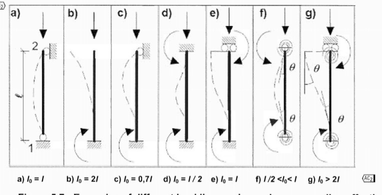
EN. 1992.1.1.2004 gives, at least, three distinct methods to determine the effective length of column. The simplest of the approaches is to use fig 5.7 of the code which is reproduced here below. The diagram shows different isolated columns with varying boundary conditions and their associated effective length.
Another method and perhaps the most popular in various reference books is the formula method given in clause 5.8.3.2 (3) of the code. This is most suitable for columns in typical frames. These formulas consider the relative stiffness of the column to the beams framing into it. The formulas for braced and unbraced situations are as shown below:
For braced members:
$
_{\,\,l_0=0.5l\sqrt{\left( \text{1}+\,\,\frac{K_1}{\text{0.45}+\,\,K_1} \right) \left( \text{1}+\,\,\frac{K_2}{\text{0.45}+\,\,K_2} \right)}}
$
For Unbraced members, the larger of the two below formulas is used:
$
l_{o\,\,}=\,\,I\sqrt{\text{1}+\,\,10\left( \frac{K_{\text{1}}x\,\,K_2}{K_1+\,\,K_2} \right)}
$
or
$
l_{o\,\,}=\,\,I\left( \text{1}+\,\,\frac{K_1}{\text{1}+\,\,K_1} \right) \left( \text{1}+\,\,\frac{K_2}{\text{1}+\,\,K_2} \right)
$
Where: K1 and K2 are the rotational stiffness of the top and bottom ends of the column. K should be taken as zero for rigid restraint and ∞ for no restraint. However, since full rigid restraint is seldom in reality, the code suggests a limiting value of 0.1 is recommended for K1 and K2 when full rigidity is assumed.
There is another method given in clause 5.8.3.2 (7) where the effective length can be calculated using:
lo = Bw
β is a coefficient which depends on the member’s end conditions. The value of β can be obtained from table 12.1 of the code for different edge conditions. The table is specifically applicable to walls. However, for columns, β can be generally assumed to be 1 and specifically assumed to be 2 for cantilever columns.
The effective height of a column is very important as it is a factor that determines the slenderness of the column or the susceptibility of the column to buckling. In designing against buckling, the code categorizes columns into two:
- Non-Slender Column
- Slender Column
Slenderness and Limiting Slenderness
According to clause 5.8.3.2 (1), the slenderness of a column can be estimated using:
λ = lo/I
The slenderness ratio obtained using the above equation is checked against the limiting slenderness. The limiting slenderness is calculated using: λlim = (20 X A X B X C/n)
The definition of each variable in the equation is reproduced below as defined in equation (5.13N) of EC 2.
A = 11(1+0,2øef) (if øef is not known, A = 0.7 may be used)
B = (1 +2w)0.5 ( if (w) is not known, B = 1.1 may be used)
C = 1.7 – rm (If rm is not known, C = 0.7 may be used)
For unbraced column and column which much of the moment on it is due to geometric imperfections then C should be adopted as 0.7
øef = effective creep ratio; see 5.8.4 of EC2
w = Asfyd;/Acfcd; mechanical reinforcement ratio
As = total area of longitudinal reinforcement
n = NEd /Acfcd; relative normal force.
rm = Mo1/Mo2; Moment ratio. Mo1 and Mo2 are the first-order end moments. IMo2I ≥ IMo1I
When the slenderness ratio is less than the limiting slenderness, the column is considered short and second order effect is neglected. However, when the slenderness ratio is greater than the limiting slenderness, the column is treated as slender and the slenderness effect is to be considered.
Critical Design Moment in columns
In order to analyze column to obtain critical moment to be adopted for designing the member, the code suggests four methods which are:
- The general method.
- Method based on Nominal Stiffness.
- The moment magnification method
- Method based on Nominal Curvature.
The fourth method is further dealt with in this article as this is similar to that obtainable in previous British standards. In order to clearly categorize columns based on the computation of the design moment that will be adopted in sizing them assuming the moment is about a single axis, columns are better categorize into two, which are:
- Non-Slender Column
- Slender column
Non-Slender Column
The design of a short column is independent on whether it is braced or unbraced. Short columns are likely to fail by crushing so the axial load on them is always preponderance. As for the moment acting on them it is pretty straightforward.
Since MED = MoED + M2
M2 is the moment due to second-order effect and it is always insignificant in short columns. Hence, we are left with MoED which is the larger of the moments acting on the two ends of the column plus the effect of geometric imperfections. Hence, the design moment (MED ) to be adopted in designing a short column is MoED
MoED = Mo2 + e1 X Ned
Mo2 is the greater between the moment at the top and bottom of the column. ie: Mo2 = Max(IMtop I, IMbottom I.
Conversely, Mo1 is the lesser between the moments at the top and bottom of the column. Ie: Mo1 = Min(IMtop I, IMbottom I. However Mo2 is mostly used in sizing a column rather than Mo1 as it is more critical.
Hence MoED = Max(IMtop I, IMbottom I + e1 X Ned
e1 which is the eccentricity due to imperfection given by lo/400. The imperfection must not be lesser than the minimum eccentricity eo prescribed by the code. The minimum eccentricity is the greater between h/30 and 20mm. Whenever the moment due to minimum eccentricity is greater than the moment due imperfection then the equation becomes:
MoED = Mo2 + e0 X Ned
MoED = Max(IMtop I, IMbottom I + e0 X Ned
Click here to read a worked example on the design of non-sender column to Eurocode 2
Braced Slender Column
The critical moment of a slender column is obtained by adding the first-order moment, which includes the effect of imperfections, to the second-order moment induced by the slenderness of the column. This is given in clause 5.8.8.2(1) of the code as:
MED = MoED + M2
MoED and M2 are first-order moment with effect of geometric imperfection, and second-order moment respectively.
M2 = NED + e2
where: NED is the design axial force.
e2 is the deflection of the column
e2= 1/r lo2 / c
1/r is the curvature
lo is the effective length
C is the which depends on the curvature distribution.
The curvature (1/r) =Kr Ko 1/ro
Axial load correction factor (Kr)
Kr = (nu – n)/ (nu -nbal) ≤ 1
nu = 1 + ω
ω = Asfyd/Acfcd
Creep Factor (Kϴ)
Kϴ = 1+ B ϕef ≥ 1
B = 0.35 + fck/200 – ⅄/150
effective creep ratio (ϕef) = This can be easily gotten by making ϕef the subject of formular in Equ 5.13N of Eurocode 2, when A is assumed to be 0.7)
The critical moment which should be adopted as the design moment (MED) should be the greatest of:
a) Mo2 + e0 X Ned
b) Moe + M2
c) Mo1 + e0 X Ned + M2/2
Moe is the equivalent first-order moment for columns without load applied between their ends. In such a column Moe is meant to replace the differing end moments which are Mo1 and Mo2
Equation 5.32 of the code renders Moe as Moe = 0.4Mo2 + 0.6Mo1 ≥ 0.4Mo2 . Where Mo1 and Mo2 are the small and large moment in the column assuming the column is bent about a double curvature.
Click here to read a worked example on the design of sender column to Eurocode 2
Bracing Slender Column
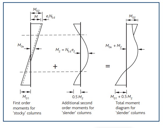
Eurocode 2 barely mention any guidance about analyses or design of bracing slender column other than the provision for its effective length. BS 8110 can be referred to for succor in computing the design moment. To obtain the design moment, the additional moment due to the second-order effect should be added to moments at its ends. This makes the equation MED = MoED + M2 to be still very much relevant.
However, MoED here can only be the first-order moment at the stiffer end plus the effect of imperfection. Below is an image from BS8110:1:1997 that perfectly captures the moment on slender columns.

If a Column is Subjected to bending about both axis (Biaxial Bending)
For most columns biaxial bending is often not always critical as large moment is both directions are seldom the case. In clause 5.8.9(3), the code gives criteria which when they are met then biaxial bending design should be ignored.
Biaxial bending should be ignored in a column when:
λy/λz ≤ 2 and λz/λy ≤ 2
And
(ey/heq)/(ez/beq) ≤ 0.2 or (ez/beq)/(ey/heq) ≤ 0.2
There is no exact method of designing biaxial column in the Eurocode but only checks which the member must conform with after it must have been designed with whatever method catches the fancy of the designer. The check that must be satisfied is given by equation (5.39) of the code where the moments acting about both axes is related to moment of resistance about both axes as thus:
$
\left( \frac{M_{Edz}}{M_{Rdz}} \right) ^{\alpha}\,\,+\,\,\left( \frac{M_{Edy}}{M_{Rdy}} \right) ^{\alpha}\,\,\leqslant \,\,1
$
Many reference books in the UK maintain biaxial column should be designed according to BS 8110 -1-1: 1997. BS 8110 -1-1 1997 permits biaxial columns to be designed to withstand an increased moment about one axis. The axis with which the moment will be increased is determined as follows:
If Mz/h’≥ My/b’ then the increased moment will be about z axis. The increased moment should be calculated thus: Mz‘ = Mz + βh’/b’ My
If Mz/h’ ≤ My/b’ then the increased moment will be about y axis. The increased moment should be calculated thus: My‘ = My + βh’/b’ Mz
Design of Columns.
In most regular columns, serviceability criteria such as deflection and cracking are not critical so the columns are mostly designed for Ultimate Limit State of strength.
Most columns are practically always subjected to both axial stress and bending stress even if the bending stress is nominal. There are different methods that can be used in designing columns some of which are listed below:
- Approximate equations
- Column design Charts
- Using M-N Interaction Diagram or Capacity Curve.
Reinforcement Detailing
- A minimum of four bars is required in a rectangular column while a minimum of six bars is required in a circular column.
- The longitudinal bar diameter must not be less than 12mm
- The minimum area of steel is given by As = 0.1NED /0.87fyk ≥ 0.002Ac
- Maximum Area of steel is Asmax < 0.04Ac
- Maximum Area of steel is Asmax < 0.08Ac
- Minimum size of links equal 0.25 x the diameter of the compression reinforcement but not less than 6mm
- Every main bar in a corner should be firmly held by a link.
- Maximum spacing should not be greater than smallest longitudinal bars x 20 or the smaller of sides of the column’s cross-section or 400mm
References:
BS EN 1992-1-1:2004: Design of concrete structures Part 1: General rules and rules for building
Someone necessarily lend a hand to make severely posts
I would state. That is the first time I frequented your website page and so far?
I amazed with the analysis you made to make this particular submit extraordinary.
Excellent task!
Hey there! Would you mind if I share your blog with my zynga group?
There’s a lot of people that I think would
really enjoy your content. Please let me know. Many thanks
hello there and thank you for your info – I have definitely picked up anything new from right here.
I did however expertise a few technical issues using this
site, since I experienced to reload the website
lots of times previous to I could get it to load correctly.
I had been wondering if your hosting is OK?
Not that I’m complaining, but slow loading instances times will sometimes affect your placement in google and could damage your high quality score
if ads and marketing with Adwords. Anyway I am adding this RSS to my e-mail and
can look out for much more of your respective exciting content.
Make sure you update this again soon.
Thanks for a marvelous posting! I quite enjoyed reading it, you will
be a great author. I will be sure to bookmark your blog and
definitely will come back very soon. I want to encourage
you to continue your great posts, have a nice weekend!
Can I simply say what a comfort to uncover a person that genuinely understands what they’re discussing on the net.
You definitely understand how to bring an issue
to light and make it important. More and more people really need to look at this and understand this side of your story.
I was surprised you’re not more popular given that you most
certainly possess the gift.
I loved as much as you will receive carried out right here.
The sketch is attractive, your authored material stylish.
nonetheless, you command get got an shakiness over that you wish
be delivering the following. unwell unquestionably come
more formerly again since exactly the same nearly a lot often inside case you shield this increase.
Hey very interesting blog!
Why people still use to read news papers when in this technological world all is
accessible on web?
I quite like looking through a post that will make men and women think.
Also, thanks for allowing for me to comment!
Admiring the dedication you put into your website and in depth
information you provide. It’s good to come across a
blog every once in a while that isn’t the same outdated rehashed material.
Great read! I’ve saved your site and I’m adding
your RSS feeds to my Google account.
What a information of un-ambiguity and preserveness of precious familiarity regarding unpredicted feelings.
Magnificent beat ! I would like to apprentice while you amend your website, how can i subscribe for a blog website?
The account aided me a acceptable deal. I had been a
little bit acquainted of this your broadcast offered bright clear idea
Hey There. I discovered your weblog the usage of msn. That is a very well
written article. I’ll make sure to bookmark it and return to read extra of your helpful information. Thank you for the post.
I will definitely comeback.
Oh my goodness! Impressive article dude! Thank you so
much, However I am experiencing troubles with your RSS.
I don’t understand why I cannot join it. Is there anybody having similar RSS problems?
Anybody who knows the answer can you kindly respond?
Thanx!!
Hi there! This post could not be written any better!
Reading this post reminds me of my good old room mate!
He always kept talking about this. I will forward this
write-up to him. Fairly certain he will have a good read.
Thanks for sharing!
This site certainly has all the information I needed concerning this
subject and didn’t know who to ask.
Thanks in favor of sharing such a pleasant thinking, post is fastidious,
thats why i have read it completely
I just like the valuable info you supply in your articles. I’ll bookmark your weblog and take a look at once more here
regularly. I’m rather certain I’ll be told a lot of new stuff right here!
Good luck for the next!
Your mode of describing everything in this paragraph is actually nice, every one be capable of effortlessly understand it, Thanks a lot.
An outstanding share! I’ve just forwarded this onto a coworker who was conducting a little homework
on this. And he actually ordered me breakfast due to the fact that I stumbled upon it for him…
lol. So allow me to reword this…. Thank YOU for the
meal!! But yeah, thanx for spending the time to talk about this issue here on your website.
Hey there, You’ve done an incredible job. I’ll definitely digg it
and personally recommend to my friends. I’m sure they’ll be benefited from this
site.
Hey very interesting blog!
Hi! I just wanted to ask if you ever have any issues with hackers?
My last blog (wordpress) was hacked and I ended up
losing many months of hard work due to no backup.
Do you have any methods to prevent hackers?
Thanks for the marvelous posting! I seriously enjoyed reading it, you can be a great author.I will remember to bookmark your blog and definitely will come back from now on. I want to encourage you continue your great writing, have
a nice evening!
I have been browsing online more than 2 hours today, yet
I never found any interesting article like yours. It’s pretty worth
enough for me. Personally, if all webmasters and bloggers
made good content as you did, the net will be a lot more useful than ever before.
Its like you read my mind! You appear to know a lot about this, like you wrote the book in it
or something. I think that you could do with a few pics to drive the message home
a bit, but instead of that, this is fantastic blog.
A fantastic read. I will certainly be back.
An impressive share! I’ve just forwarded this onto a colleague who had
been doing a little research on this. And he actually bought me breakfast simply because I stumbled upon it for him…
lol. So let me reword this…. Thanks for the meal!! But yeah, thanx for
spending some time to discuss this subject here on your blog.
When someone writes an paragraph he/she keeps the plan of
a user in his/her mind that how a user can be aware of it.
So that’s why this article is great. Thanks!
Wow, this piece of writing is good, my sister is analyzing such things, therefore I am going to let
know her.
Thank you for the auspicious writeup. It in fact was
a amusement account it. Look advanced to more added agreeable from you!
By the way, how could we communicate?
Hello there, I discovered your blog by way of
Google while looking for a related topic, your web site came
up, it seems good. I’ve bookmarked it in my google bookmarks.
Hello there, just become alert to your weblog thru Google,
and located that it is truly informative. I’m gonna be careful for brussels.
I’ll appreciate if you happen to proceed this in future. A lot of people will likely be benefited out of your writing.
Cheers!
It’s actually a great and helpful piece of information. I’m glad that you simply shared this helpful information with us.
Please keep us up to date like this. Thank you for sharing.
Do you have a spam issue on this blog; I also am a blogger, and I was wanting to know your
situation; we have created some nice methods and we are looking to swap methods with others, please shoot me an email if interested.
Whoa! This blog looks exactly like my old one!
It’s on a completely different subject but
it has pretty much the same page layout and design. Outstanding choice of colors!
When some one searches for his essential thing, thus he/she wants to
be available that in detail, thus that thing is maintained over here.
Hello there, You have done an incredible job. I will definitely digg it and personally recommend
to my friends. I’m sure they will be benefited from this web site.
If you would like to grow your knowledge simply keep visiting
this site and be updated with the hottest news posted here.
I do not even know how I ended up here, but I
thought this post was good. I do not know who you are but certainly you are going
to a famous blogger if you are not already 😉 Cheers!
My spouse and I stumbled over here from a different website and
thought I might as well check things out. I like what I see so now
i am following you. Look forward to checking out your web page
for a second time.
Nice post. I was checking continuously this blog and I am inspired!
Very helpful information specifically the ultimate part 🙂 I care for
such info a lot. I was looking for this particular info
for a long time. Thanks and best of luck.
Valuable information. Lucky me I found your website accidentally, and I am shocked why this
twist of fate didn’t came about in advance! I bookmarked
it.
Its like you read my thoughts! You appear to know so much approximately
this, such as you wrote the ebook in it or something. I think that you can do with some percent to power
the message house a bit, but other than that, this
is excellent blog. A great read. I’ll definitely be back.
Usually I don’t learn post on blogs, but I would like to say
that this write-up very pressured me to try and do it!
Your writing taste has been surprised me. Thank you, very great article.
you’re truly a just right webmaster. The website loading velocity is incredible.
It seems that you’re doing any unique trick. In addition, The
contents are masterwork. you have performed a excellent activity in this topic!
I could not resist commenting. Perfectly written!
When I initially commented I clicked the “Notify me when new comments are added” checkbox and now each time a comment is added I
get four emails with the same comment. Is there any way you can remove me from that service?
Many thanks!
I’m curious to find out what blog system you’re utilizing?
I’m having some minor security problems with my latest site and I would like to find something more risk-free.
Do you have any recommendations?
Very shortly this site will be famous among all blogging and site-building visitors, due to it’s pleasant articles
whoah this blog is fantastic i love reading your posts.
Keep up the great work! You understand, lots of individuals are searching around for this info,
you could help them greatly.
You really make it seem so easy with your presentation but
I find this topic to be really something that I think I would never understand.
It seems too complex and very broad for me. I am
looking forward for your next post, I’ll try to get the hang of it!
It’s amazing in favor of me to have a website,
which is valuable in favor of my experience. thanks admin
I’m not sure exactly why but this web site is loading very slow for me.
Is anyone else having this issue or is it a problem on my end?
I’ll check back later on and see if the problem still exists.
I used to be recommended this website via my cousin. I’m not positive whether this publish is written by means of him as no one else understand such distinctive
approximately my trouble. You are wonderful! Thanks!
Hi there would you mind letting me know which web host
you’re working with? I’ve loaded your blog in 3 different web browsers and I must say this blog
loads a lot quicker then most. Can you suggest a good internet hosting provider at a reasonable price?
Kudos, I appreciate it!
Hello there! This post couldn’t be written any better!
Reading this post reminds me of my previous room mate!
He always kept chatting about this. I will forward this article
to him. Fairly certain he will have a good read. Many thanks for sharing!
Very good blog post. I absolutely appreciate this website.
Continue the good work!
I always emailed this web site post page to all my contacts, for the reason that if like to read it afterward my contacts will too.
Wow! Finally I got a webpage from where I be able to genuinely take
helpful data concerning my study and knowledge.
Discovering your article has been a pleasure.
Brimming with insightful content and thought-provoking commentary, which is a rarity these days.
appreciate the effort you’ve put into your work.
Your article is refreshingly unique. You bring a novel viewpoint that has sparked my interest.
I’m eager to seeing what you post next.
I simply had to leave a comment. Your posts speak with me on a personal level.
If you’re thinking about offering a newsletter, sign me
up! It would be a pleasure to have your insights sent right to my inbox.
Your post struck a chord with me. Rarely do you come across a piece that encourages you to ponder.
Keen to see more of your work and urge you to carry
on with your passion.
Your blog post felt like a breath of fresh air. With so much noise online,
it’s fantastic to read content that’s as engaging and educational as yours.
Keep it up
This syntax provides a variety of options for creating a positive
and encouraging blog comment that compliments the author’s work and expresses a desire to continue engaging with their content.
Every once in a while, I come across a blog that truly stands out because of its thought-provoking articles.
Yours is without a doubt one of those rare gems. The way you blend your words is not just informative but also remarkably entertaining.
I applaud the dedication you show towards your craft and eagerly look forward to your future posts.
Amidst the vastness of the internet, it’s a pleasure to find a blogger who invests genuine passion into their work.
Your posts not only offer valuable insights but also
spur meaningful dialogue. Please consider me a lifelong fan from this point forward.
Your blog has quickly risen to the top of
my list for me, and I find myself visit it
frequently for fresh insights. Each post is like a masterclass in your
niche, delivered with clarity and wit. Could you starting a subscription service or a periodic newsletter?
I am keen to get more of your wisdom directly to my inbox
Your unique perspective to issues is not only
refreshing, it’s deeply needed in today’s internet landscape.
Your ability to break down complex concepts and share them
in an understandable way is a talent that
should be celebrated. I look forward to your next article and
the discussions they’ll inspire.
It’s rare to find a blog that acts as both a brain gym and a soulful dialogue.
Your posts accomplish that, offering a rich blend
of intellectual stimulation and personal connection. The
readership you’re building here is testament to your effect and proficiency.
I’m anxious to see where you’ll take us
next and I’ll be following along closely.
Upon spending several hours exploring the depths of the internet today, I must say that your blog is like an oasis of insight.
Never before have I encountered such a collection of
intriguing content that resonate on a profound level. Your ability
for clarifying complex subjects with elegance and sharpness is admirable.
I’m enthusiastically waiting for your upcoming article, anticipating it will enhance my understanding even further.
In our modern digital age, where content saturation is the norm, your blog emerges as a cornerstone
of genuine content creation. It’s a rarity to find a corner of the web that commits to fostering mindful learning.
Your articulate posts stimulate a desire for learning
that many of us long for. I would be honored if there’s a possibility to
subscribe for direct notifications, as I would hate to miss even one thought-provoking post.
Your website is the epitome of what dedicated blogging can achieve.
Every post you create is brimming with actionable takeaways and meaningful stories that leave
me pondering long after I’ve left the page. Your perspective is a
much-needed addition to the frequently crowded digital
landscape. In the event you create an exclusive community, count me as an eager participant
to join. Your writing is deserving of following.
I find myself returning to your blog repeatedly, drawn by the
standard of discourse you foster. It’s evident
that your blog is more than a medium for sharing concepts;
it’s a community for thinkers who desire meaningful engagement.
Your investment inOf course!
As soon as I began reading your blog, I realized it was something unique.
Your skill to plunge into challenging topics and unravel them
for your readership is truly noteworthy. Each post
you release is a repository of information, and I always find myself excited to discover what you’ll explore next.
Your commitment to quality is evident, and I anticipate that you’ll continue offering such invaluable perspectives.
Your posts is a lighthouse in the sometimes
turbulent seas of online content. Your deep dives into diverse subjects are not only informative but also incredibly engaging.
I appreciate the way you combine meticulous investigation with relatable examples, creating posts that are both informative
and entertaining. If there’s a method to follow your blog or become part of a newsletter subscription, I
would be grateful to be informed of your latest
musings.
As a content creator, I’m spurred by the enthusiasm you
inject into each blog entry. You have a talent for making even the most complex topics approachable and compelling.
The way you break down concepts and link them to wider narratives is
incredibly skillful. Kindly inform me if you have any webinars or e-books
in the works, as I would be eager to learn from your expertise.
It’s uncommon to encounter a blog that strikes the perfect chord with both intellect
and emotion. Your articles are crafted with a degree of thoughtfulness that addresses the core of the human experience.
Every time I visit your blog, I come away feeling enriched and inspired.
I’m eager to know whether you have plans to
From the moment I started perusing your blog, I knew it was something unique.
Your skill to delve into challenging topics and clarify them for your
readership is truly remarkable. Each entry you release is a treasure trove of information, and I always find myself eager to discover what you’ll uncover next.
Your dedication to high-quality content is evident, and I trust that you’ll keep
on providing such invaluable perspectives.
Simply wish to say your article is as astonishing.
The clarity in your post is just excellent and i can assume you are an expert on this subject.
Fine with your permission let me to grab your RSS feed to keep up to date with forthcoming post.
Thanks a million and please carry on the enjoyable work.
Coming across your blog has been a pleasure.
Packed with insightful content and witty commentary, which is a rarity these days.
value the time you’ve put into your writing.
Your article is refreshingly unique. You bring a fresh take that is sparked my interest.
Looking forward to seeing what you post next.
I just couldn’t resist to leave a comment. Your articles resonate with
me on a profound level. If you’re thinking about offering a newsletter, sign me
up! It would be a joy to have your insights sent right to
my inbox.
Your article struck a chord with me. It’s not every day you come across a piece that prompts you to reflect.
Keen to read more of your work and urge you to keep writing.
Your blog post was a refreshing change. With an overwhelming amount of information online, it’s great to encounter content that’s as meaningful
and articulate as yours. Keep it up
This syntax provides a variety of options for creating a positive and encouraging blog comment that
compliments the author’s work and expresses a desire to continue engaging with their content.
Occasionally, I stumble upon a blog that truly stands out due to its
compelling content. Yours is undoubtedly one of those rare gems.
The way you weave your words is not just informative but also
remarkably entertaining. I applaud the dedication you show towards your craft and eagerly await your future
posts.
In the vast expanse of the digital world, it feels rewarding to come
across a creator who puts considerable effort into their work.
Your posts don’t just provide useful information but also stimulate meaningful
dialogue. Please consider me a lifelong fan from this point forward.
Your blog has become a go-to resource for me, and I find myself check it frequently for new content.
Each post is like a tutorial in your niche, presented with eloquence and charm.
Might you creating a subscription service or a monthly newsletter?
I am keen to get more of your knowledge straight to my inbox
Your distinctive approach to subjects is truly refreshing,
it’s immensely appreciated in the modern digital landscape.
Your ability to break down complex concepts and share them in a user-friendly
way is an ability that should not go unnoticed. I am excited
for your future publications and the conversations they’ll
ignite.
Finding a blog that serves both a brain gym and a soulful
dialogue. Your posts do just that, providing a
harmonious blend of knowledge and emotional resonance.
The audience you’re building here is testament to your
impact and authority. I’m anxious to see where you’ll take us next and I’m
all in for the ride.
Having dedicated countless hours diving into the depths of the internet today, I must say that your blog is like an oasis of insight.
Never before have I stumbled upon such a collection of
compelling ideas that resonate on a substantial level.
Your penchant for clarifying complex subjects with elegance and
sharpness is admirable. I’m patiently waiting for your upcoming publication, anticipating it will enhance my understanding even further.
In our modern digital age, where information overload is common, your
blog emerges as a pillar of genuine content creation. It’s a joy to discover a space of the web that is dedicated to developing intellectual growth.
Your articulate posts stimulate a yearning for understanding that many of us crave.
I would be honored if there’s a way to subscribe for direct notifications, as I wouldn’t want
to miss any enlightening entry.
Your online presence is the epitome of what passionate writing
is all about. Each article you compose is laden with valuable takeaways and rich narratives that keep me thinking long after I’ve read them.
Your voice is a refreshing voice to the often noisy digital landscape.
Should you decide to an exclusive subscription, count me as an eager participant to join. Your writing is worth sustaining.
I find myself returning to your blog time
and again, drawn by the standard of conversation you foster.
It’s clear that your blog isn’t just a medium for sharing
thoughts; it’s a community for like-minded individuals who desire meaningful engagement.
Your investment inOf course!
When I started perusing your blog, I realized it was something extraordinary.
Your ability to plunge into challenging topics and unravel them
for your readership is truly impressive. Each entry
you release is a repository of knowledge, and I constantly find
myself excited to see what you’ll uncover next. Your dedication to quality is apparent, and I anticipate that you’ll keep
on providing such valuable content.
Your blog is a guiding light in the sometimes turbulent seas of online content.
Your deep dives into varied subjects are not only informative but also immensely engaging.
I appreciate the way you balance thorough research with personal anecdotes, crafting posts that are equally
enlightening and enjoyable. If there’s an opportunity to
follow your blog or join a newsletter subscription, I would be delighted to be informed
of your latest musings.
As a blogger, I’m spurred by the zeal you put into each post.
You have a gift for making even the most obscure topics accessible and intriguing.
The way you dissect information and relate them to
wider narratives is exceptionally artful. Please inform me if you have any workshops or digital resources in the works, as I would love to learn from your expertise.
It’s uncommon to find a blog that strikes the perfect chord with both
heart and mind. Your articles are written with a
degree of thoughtfulness that addresses the core of the human experience.
Each time I check your blog, I leave feeling enriched and motivated.
I’m keen to know whether you plan to
As soon as I started perusing your blog, I could tell it was something special.
Your talent to plunge into intricate topics and clarify
them for your audience is truly impressive. Each post you share
is a wealth of information, and I always find myself anxious to read what you’ll explore next.
Your commitment to quality is apparent, and I trust that you’ll continue sharing such precious insights.
Finding your website made my day. Packed with knowledgeable content and witty commentary, which
is a rarity these days. cherish the time you’ve put into your writing.
Your post is impressive. You present a fresh take that is
sparked my interest. I’m eager to seeing what you post next.
I simply had to leave a comment. Your content
shine with me on a personal level. If you’re considering offering a
newsletter, sign me up! It would be a pleasure to have your insights sent right to my inbox.
Your article struck a chord with me. Rarely do you come across a website that encourages you to think deeply.
Eager to read more of your work and urge you to continue sharing.
Your blog post was an eye-opener. With so much noise online, it’s great
to find content that’s as meaningful and articulate as yours.
Looking forward to more
This syntax provides a variety of options for creating
a positive and encouraging blog comment that compliments the
author’s work and expresses a desire to continue engaging with
their content.
From time to time, I discover a blog that grabs my interest
because of its thought-provoking articles.
Yours is certainly one of those rare gems. The way you blend your words is not just informative but also extremely captivating.
I commend the dedication you show towards your craft and eagerly anticipate your future
posts.
In the plethora of the digital world, it’s a pleasure to come across a
blogger who invests genuine passion into their work. Your posts don’t just offer
knowledgeable takeaways but also stimulate thoughtful conversations.
Count me in as a regular reader from this point forward.
Your blog has quickly risen to the top of my list for me, and I can’t help but visit it regularly for new content.
Each post is like a lesson in the topic at hand, presented with eloquence and charm.
Could you offering a subscription service or a periodic newsletter?
I would be thrilled to get more of your knowledge directly
to my inbox
The unique angle you bring to subjects is not only refreshing,
it’s immensely appreciated in our current online landscape.
Your ability to dissect complex concepts and share them in an understandable way is a talent that should not go unnoticed.
I look forward to your upcoming posts and the conversations they’ll inspire.
It’s rare to find a blog that serves both a brain gym and a soulful dialogue.
Your posts do just that, offering a rich blend of knowledge and emotional
resonance. The audience you’re building here is proof to your influence and
expertise. I’m anxious to see where you’ll take us
next and I’m all in for the ride.
After investing countless hours diving into the expanse of the internet today, I must say
that your blog is like a beacon of knowledge. Not once have I stumbled upon such a collection of compelling ideas that resonate on a substantial level.
Your ability for clarifying complex subjects with elegance and keen insight
is worthy of admiration. I’m eagerly waiting for your subsequent
publication, believing it will deepen my understanding even further.
In today’s age of information, where content is plentiful, your blog shines as a bastion of authenticity.
It’s a privilege to behold a corner of the web that commits to developing knowledge expansion. Your eloquently written posts ignite a
yearning for understanding that many of us seek. I would be honored if there’s a possibility to sign up for direct notifications, as I wouldn’t want to miss a single thought-provoking article.
Your blog is a testament to what dedicated blogging should be.
Each entry you compose is laden with priceless takeaways and deep insights that leave me pondering long after I’ve left the page.
Your perspective is a refreshing voice to the often noisy online world.
If you have an exclusive membership, count me as an eager participant to
join. Your content is meriting supporting.
I find myself returning to your blog time and again, drawn by the caliber
of discussion you foster. It’s clear that your blog is not merely a
medium for sharing ideas; it’s a hub for like-minded individuals who are in search of purposeful engagement.
Your commitment toOf course!
From the moment I began reading your blog, I realized it was something special.
Your ability to dive into challenging topics and demystify them for your readers is truly impressive.
Each entry you publish is a repository of insights, and I
constantly find myself excited to discover what you’ll explore next.
Your commitment to excellence is apparent, and I anticipate that you’ll
continue sharing such precious perspectives.
Your blog is a lighthouse in the sometimes turbulent seas of
online content. Your in-depth analysis into varied subjects are not only educational but also extremely absorbing.
I admire the way you balance detailed study with relatable examples,
crafting posts that are both informative and enjoyable.
If there’s an opportunity to subscribe your blog
or become part of a newsletter subscription, I would
be delighted to be notified of your latest
musings.
As a content creator, I’m motivated by the zeal you put
into each article. You have a knack for making even the most obscure topics approachable and intriguing.
The way you break down information and relate them to larger contexts is
exceptionally masterful. Please inform me if you have any online courses or digital resources in the works, as I would be eager to
gain further insight from your expertise.
It’s not often to encounter a blog that strikes the perfect chord with
both the intellectual and the personal. Your articles are penned with a level of insight
that touches the core of the human condition. Every time I read your blog, I leave more informed and stimulated.
I’m curious to know whether you plan to
When I commenced reading your blog, I realized it was something unique.
Your talent to delve into challenging topics and demystify them for your
readers is truly remarkable. Each entry you publish is a repository of
insights, and I always find myself anxious to read what you’ll uncover next.
Your commitment to high-quality content is clear, and I hope that you’ll
keep on sharing such valuable perspectives.
I have been browsing online greater than 3 hours today, but I by no means discovered
any fascinating article like yours. It’s pretty price sufficient for me.
In my view, if all web owners and bloggers made excellent content as you did, the internet shall be much more useful than ever before.
Everything is very open with a very clear explanation of the challenges.
It was definitely informative. Your website is very useful.
Thank you for sharing!
This piece of writing is in fact a pleasant one it helps new internet viewers,
who are wishing in favor of blogging.
Howdy! Quick question that’s totally off topic. Do you know how
to make your site mobile friendly? My blog looks weird when viewing from my apple iphone.
I’m trying to find a theme or plugin that might be able to correct this issue.
If you have any suggestions, please share. Cheers!
Howdy would you mind letting me know which webhost you’re using?
I’ve loaded your blog in 3 different internet browsers and I must say this blog loads
a lot quicker then most. Can you recommend a good hosting provider at a fair price?
Cheers, I appreciate it!
Hello Dear, are you in fact visiting this website
regularly, if so afterward you will without doubt take nice know-how.
Hi there, just wanted to mention, I enjoyed this post.
It was inspiring. Keep on posting!
I’m not that much of a internet reader to be
honest but your sites really nice, keep it up! I’ll go ahead and bookmark your website to come back down the road.
Cheers
Hey there, You have done an incredible job.
I will certainly digg it and personally recommend to my friends.
I’m sure they’ll be benefited from this web site.
Its like you read my mind! You appear to know a lot about this, like you wrote the book in it or something.
I think that you could do with a few pics to drive the message home a bit, but instead
of that, this is excellent blog. A fantastic read.
I’ll certainly be back.
It’s very trouble-free to find out any matter on web as compared
to textbooks, as I found this paragraph at
this site.
I like what you guys are up too. This kind of clever work and
reporting! Keep up the fantastic works guys I’ve you guys to blogroll.
I am sure this piece of writing has touched all the internet viewers, its really really pleasant post
on building up new web site.
It’s amazing to pay a visit this web page and reading the views of all
colleagues regarding this piece of writing, while I am also keen of getting experience.
Thanks for finally talking about > Design of Reinforced Concrete Column to Eurocode 2 – an overview – First Principle
Engineering < Liked it!
I have to thank you for the efforts you’ve put in penning this website.
I am hoping to see the same high-grade content from you later on as well.
In fact, your creative writing abilities has motivated me to get my own site now 😉
Its not my first time to visit this site, i am browsing this
web page dailly and obtain pleasant information from here all the time.
Hi! Do you know if they make any plugins to assist with Search Engine
Optimization? I’m trying to get my blog to rank for some targeted keywords but I’m not seeing
very good results. If you know of any please share.
Appreciate it!
Thanks designed for sharing such a fastidious opinion, piece of writing is fastidious, thats why i have read it
entirely
I blog often and I really appreciate your information. Your article has truly peaked my interest.
I will bookmark your site and keep checking for new information about once a week.
I opted in for your RSS feed too.
Simply wish to say your article is as astonishing.
The clearness on your put up is simply excellent and that i
could suppose you’re a professional in this subject.
Well with your permission let me to take hold of
your feed to keep updated with coming near near post.
Thanks 1,000,000 and please keep up the rewarding
work.
Great blog! Is your theme custom made or did you download it from somewhere?
A design like yours with a few simple adjustements would really make my blog jump out.
Please let me know where you got your theme. With thanks
I visited several websites however the audio feature for audio songs present at this
web page is in fact wonderful.
This paragraph provides clear idea designed for the
new people of blogging, that genuinely how to do running a blog.
Howdy! I simply wish to offer you a huge thumbs
up for your excellent information you’ve got right here
on this post. I am coming back to your web site for more soon.
Ahaa, its good discussion concerning this paragraph here at
this web site, I have read all that, so now me also commenting here.
Great blog here! Also your website loads up fast! What host are you using?
Can I get your affiliate link to your host?
I wish my web site loaded up as quickly as yours lol
What a stuff of un-ambiguity and preserveness of valuable know-how regarding unexpected feelings.
Attractive section of content. I just stumbled upon your
site and in accession capital to assert that I
acquire actually enjoyed account your blog posts. Any way I will be subscribing to your feeds and even I achievement you access consistently rapidly.
I’m impressed, I must say. Rarely do I encounter a
blog that’s both educative and interesting, and let me tell you, you have
hit the nail on the head. The issue is an issue that not enough folks
are speaking intelligently about. Now i’m very happy I found this
in my hunt for something regarding this.
hi!,I like your writing very a lot! percentage we communicate extra about your post on AOL?
I require an expert in this area to resolve my problem.
Maybe that is you! Taking a look forward to peer you.
We’re a group of volunteers and starting a brand new scheme in our community.
Your web site provided us with helpful info to work on.
You have performed an impressive job and our whole group might be thankful to you.
Hi there, I want to subscribe for this webpage to take most recent
updates, therefore where can i do it please assist.
Quality articles or reviews is the main to invite the people to go to see the web page,
that’s what this web site is providing.
Ridiculous quest there. What happened after?
Thanks!
Attractive section of content. I just stumbled upon your site and in accession capital to assert that I acquire in fact enjoyed account
your blog posts. Any way I will be subscribing to your augment and
even I achievement you access consistently fast.
Hello, i feel that i noticed you visited my weblog so
i got here to return the prefer?.I’m trying to in finding things
to improve my web site!I guess its adequate to make use of some of your concepts!!
Definitely consider that that you said. Your favourite
justification seemed to be at the web the easiest factor
to take note of. I say to you, I definitely get annoyed even as other folks consider
issues that they plainly do not understand about.
You controlled to hit the nail upon the highest and defined
out the entire thing without having side effect ,
other people can take a signal. Will probably be again to
get more. Thanks
Nice post. I used to be checking constantly this blog and I’m inspired!
Extremely useful info particularly the ultimate phase 🙂 I care
for such information a lot. I was looking for this certain info for a long time.
Thank you and best of luck.
One thing I’d really like to say is always that car insurance termination is a dreaded experience and if you are doing the best things being a driver you simply won’t get one. Some individuals do obtain notice that they have been officially dumped by their own insurance company they then have to fight to get added insurance after a cancellation. Affordable auto insurance rates are frequently hard to get after the cancellation. Knowing the main reasons concerning the auto insurance cancellation can help individuals prevent getting rid of in one of the most vital privileges out there. Thanks for the suggestions shared through your blog.
I do agree with all the ideas you have presented in your post. They’re very convincing and will definitely work. Still, the posts are very short for novices. Could you please extend them a little from next time? Thanks for the post.
I read this paragraph fully regarding the resemblance of most recent and preceding technologies, it’s amazing article.
Hi there, just became aware of your blog through Google, and found that
it’s truly informative. I’m going to watch out for brussels.
I’ll appreciate if you continue this in future. Numerous people will be benefited from your writing.
Cheers!
Howdy! Do you know if they make any plugins to protect against
hackers? I’m kinda paranoid about losing everything
I’ve worked hard on. Any recommendations?
You can certainly see your expertise in the paintings you write. The sector hopes for more passionate writers such as you who are not afraid to say how they believe. Always go after your heart. “No man should marry until he has studied anatomy and dissected at least one woman.” by Honore’ de Balzac.
I was wondering if you ever considered changing the structure of
your site? Its very well written; I love what youve got to say.
But maybe you could a little more in the way of content so people could connect with it better.
Youve got an awful lot of text for only having one or 2 images.
Maybe you could space it out better?
I’m really enjoying the design and layout of your blog.
It’s a very easy on the eyes which makes it much more enjoyable for me to come here and
visit more often. Did you hire out a designer to create your
theme? Excellent work!
Hey there would you mind sharing which blog platform
you’re working with? I’m planning to start my own blog soon but I’m having a difficult
time deciding between BlogEngine/Wordpress/B2evolution and
Drupal. The reason I ask is because your design and style seems different then most blogs and I’m looking for something unique.
P.S Apologies for getting off-topic but I had to ask!
Hey very nice blog!