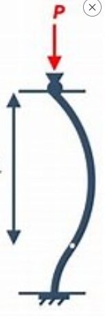
A slender column is a column that is vulnerable to buckling which prevents it from harnessing its maximum strength. Several codes of practice have devised diverse methods to analyse this type of column with focus on stimulating its inherent instability by augmenting the moments from the general first-order analysis with additional moment. This will enable the column to be designed and sized appropriately for the most onerous case throughout its service life.
The Eurocode 2 also has several methods of analysing a slender column, however the method favored in this article shall be the nominal curvature method as discussed in clause 5.8.8 of the code. Hence, this article presents a worked example of design of slender column to Eurocode 2 using the nominal curvature method.
Worked Example
The column that shall be designed is column BD that has already been analysed here for moment as part of a frame. Since the column has already been evaluated to be subjected to a moment of 42.302KNm, we are left to evaluate the axial force acting on the column.
The axial force of a column in a structural frame may be calculated on the assumption that beams and slabs transmitting force into the particular column are simply supported. By this, the reaction from the column can be calculated which in turn serves as the load on the column. The axial force on the column BD is calculated below.
Computation of Axial load
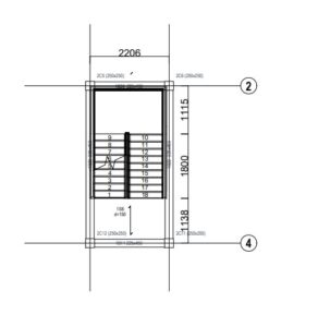
For easy computation of axial load, the analysed frame is reproduced below:
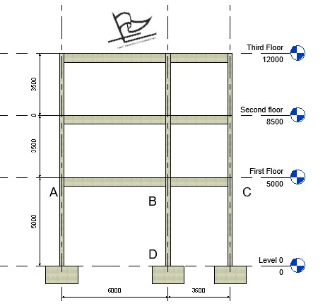
Since we are computing for the axial load, the maximum ultimate load is used all through as this gives the unfavorable axial load possible.
Third Floor Load take down
Characteristic permanent load on beam (gk) = 23KN/m
Characteristic variable load on beam (qk) = 36KN/m
Maximum ultimate Load acting on beam = 1.35(23) + 1.5(36) = 85KN/m
Load from third floor to column BD = (6/2 + 3.5/2) X 85 = 403.75KN
Second Floor and First Floor Load take down
Characteristic permanent load on beam (gk) = 100KN/m
Characteristic variable load on beam (qk) = 40KN/m
Maximum ultimate Load acting on beam = 1.35(40) + 1.5(100) = 195KN/m
Load from second floor to column BD = (6/2 + 3.5/2) X 195 = 926.25KN
Load from first floor to column BD = (6/2 + 3.5/2) X 195 = 926.25KN
Axial Load on Column BD Total Axial load on column BD = 403.75 + 926.25 + 926.25 = 2256.25KN
Steps in designing the column
Having calculated the axial load on the column, we can now proceed with the design of the column. However, before embarking on the proper design, let us write down the loads and other design parameters necessary for the column design.
Moment on the column (M) = 42.302KNm
Axial load on the column (N) = 2256.25KN
Length (l) = 5m
Breadth (b) = 250mm
Height (h) = 250mm
fck = 25N/mm2
cover = 25mm
1. Check the Slenderness of the column.
The slenderness ratio of the column shall be compared against the limiting slenderness, if the slenderness ratio is greater than the limiting slenderness then the column is declared “slender”. The column is declared “non-slender” if otherwise. This is shown in the below steps
a) Calculate the effective length of the column
Since the column is braced, the Effective length (lo) is calculated thus:
$ _{\,\,l_0=0.5l\sqrt{\left( \text{1}+\,\,\frac{K_1}{\text{0.45}+\,\,K_1} \right) \left( \text{1}+\,\,\frac{K_2}{\text{0.45}+\,\,K_2} \right)}} $
K1 and K2 are the relative flexibilities of the top and bottom ends respectively
K1= $ \frac{\frac{\varSigma I_c}{l}}{\frac{\varSigma 2EI_b}{l}} $
$ \frac{\frac{\frac{bh^3}{12}}{l}}{2X\frac{\frac{bh^3}{12}}{l}\,\,+\,\,2X\frac{\frac{bh^3}{12}}{l}} $
$ \frac{\frac{\frac{250 X 250^3}{12}}{5000}}{2X\frac{\frac{225 X 500^3}{12}}{6000}\,\,+\,\,2X\frac{\frac{225 X 500^3}{12}}{3500}} $
= 65104.2/(781250 + 1339285.7)
= 0.031
We calculate K2
The bottom end of column BD is assumed fixed in the subframe which implies the flexibility is 0. However, in accordance to Eurocode 2 guidance K2 is taken as 0.1 since fully rigid restraint is rare in actual practice (check 5.8.3.2 (3))
Hence; K2= 0.1
$ _{\,\,l_0=0.5l\sqrt{\left( \text{1}+\,\,\frac{0.031}{\text{0.45}+\,\,0.031} \right) \left( \text{1}+\,\,\frac{0.1}{\text{0.45}+\,\,0.1} \right)}} $ = 2803.2mm
b) Calculate the radius of gyration
$ r\,\,=\,\,\sqrt{\frac{I}{A}}\,\,=\,\,\sqrt{\frac{\frac{bh^3}{12}}{b\,\,X\,\,h}}\,\,=\,\,\sqrt{\frac{\frac{\text{250}X\,\,250^3}{12}}{\text{250}X\,\,250}}\,\,\,\,=\,\,72.17 $
c. Calculate the slenderness ratio of the column
λ = lo/r = 2803.2mm/72.17 = 38.84
d. Calculate the limiting slenderness
λlim = (20 X A X B X C/√n)
A = 0.7, B = 1.1, C = 0.7 (All these assumptions are based on alternative suggestion by the code, check clause 5:8:3:1)
n = NEd /Acfcd
= n = 2256.25 X 10^3 / (250 X 250 X 0.85 X 25/1.5) = 1.6
λlim = (20 X 0.7 X 1.1 X 0.7/√1.6) = 16.4
Since λlim (16.4) is less than ⅄ (38.84) then the column is slender and second-order moment is required.
2. Calculate the second-order moment
Since the column is slender, second-order moment due to slenderness is necessary. Second-order moment (M2 ) = NED + e2
where: NED is the design axial force.
e2 is the deflection of the column
Calculate deflection due to slenderness
e2= 1/r lo2 / c
c = 10 (see 5:8:8:2 (4) of EC2)
e2= 1/r x 2803.22/ 10
-
Calculate the curvature (1/r)
1/r = Kr Ko 1/ro
Axial load correction factor (Kr)
Kr = (nu – n)/ (nu -nbal) ≤ 1
nu = 1 + ω
ω = Asfyd/Acfcd
Assume As to be 4y16 = 799.7mm2
fyd = 500/1.15 = 434.8
fcd = 0.85 x 25/1.5 = 14.17
ω = (799.7 x 434.8)/ (250 x 250 x 14.17) = 0.393
nu = 1+ 0.393 = 1.393
nbal = 0.4
n = Ned/Ac x fcd = 2256.25/ (250 x 250 x 0.85 x 25/1.5 ) = 0.003
Kr = (1.393 – 0.003)/ (1.393 -0.4) = 1.4
Since 1.4 > 1, then Kr is taken as 1
Creep Factor (Kϴ)
Kϴ = 1+ B ϕef ≥ 1
B = 0.35 + fck/200 – ⅄/150
= 0.35 + 25/200 – 38.84/150 = 0.216
effective creep ratio (ϕef) = 2.14 (This conservative value is gotten by making ϕef the subject of formular in Equ 5.13N of Eurocode 2, when A is assumed to be 0.7)
Kϴ = 1+ 0.216 x 2.14 = 1.462
Calculate 1/ro
1/ro = fyd/(Es x 0.45d)
434.8/ (200×10^3 x 0.45 x 250) = 0.00002
curvature (1/r) = 1 x 1.462 x 0.0002 = 0.00003
deflection due to slenderness (e2) = 0.00003 x 2803.2^2 x 10 = 26.69mm
M2 = 2256.25 x 26.69/1000 = 60.2KNm
3. Compute the design moment (MEd)
The design moment is the greatest of:
- max (Mo2, Mo1) + (NED) x max (e)
2 Moe+ M2
3. Mo1+ M2/2
Where:
Mo2 = 42.302KN
Mo1 = 0
Moe= 0.4 M02 + 0.6 M01 = 16.9KNm
M2 = 60.2KNm
- max (Mo2, Mo1) + (NED) x max (e)
= 42.302 + 2256.25 x 20/1000 = 87.427KNM
2. Moe+ M2 = 16.9 + 60.2 = 77.13KNm
3. M1+ M2/2 = 0 + 60.2/2 = 30.1KNM
The design moment is 87.427KNm
4. Use the design Chart to determine the area of reinforcement required
In order to use the design chart, few parameters have to be calculated
Determine NED/bhfck
NED/bhfck = 2256.25X 10^3 /250 X 250 X 25 = 1.44
Determine MED/bh²fck
MED/bh²fck = 87.427 X 10^6/250 X 250^2 X 25 = 0.22
Calculate d’/h
d’/h determines the exact graph that shall be used to determine the reinforcement area.
d’ = c + d/2 = 25 + 16/2 = 33
d’/h = 33/250 = 0.13
This is approximated to 0.1 and the design chart peculiar to d’/h = 0.1 is used. Fig 9b of “How to design concrete Structures to Eurocode 2” matches this. The chart is reproduced below.

From the design chart, the intersection of MED/bh²fck = 0.22 and NED/bhfck = 1.44 is outside the boundary of the curve. The curve does not even have the value of 1.44 2hich corresponds to N/bhfck as it ends at 1.3. This means the load and moment acting on the column exceeds its capacity. To circumvent this, we shall increase the height of the column (h) to 350mm. By this the column cross-section becomes 250 x 350mm
We re-determine the parameters
- Determine NED/bhfck
NED/bhfck = 2256.25 x 10^3 /250 x 350 x 25 = 1.0
2. Determine MEd/bh2fck
MEd/bh2fck = 87.427 x 10^6/250 x 350^2 x 25 = 0.11
3. Calculate d’/h
d’/h determines the exact graph that shall be used to determine the reinforcement area.
d’ = c + d/2 = 25 + 16/2
= 33
d’/h = 33/350 = 0.09
d’/h is approximated to 0.1 and the same design chart is used.
MEd/bh²fck = 0.11 and NED/bhfck = 1.0 intersects at at 0.8 on the design chart. This is shown by the red mark drawn otn the design chart as displayed below.

Hence from the design chart:
Asfyk/bhfck = 0.8
As = 0.8 x bhfck /fyk
As = 0.8 x 250 x 350 x 25/ 500
As = 3500mm2
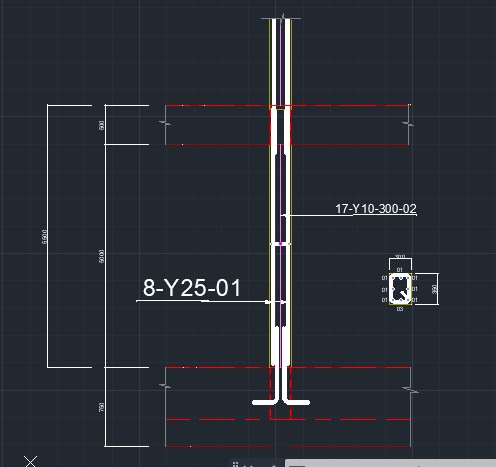
Provide 8Y25 (3905mm2) as longitudinal bars.
5. Check minimum required reinforcement
Asmin = 0.1Ned/fyd ≥ 0.002Ac
= 518.93mm2
Since Asmin (518.93mm2) < As (3905mm2), minimum area of reinforcement is satisfied.
6. Check maximum area reinforcement
Asmax= 0.4 Ac = 0.4 x 250 x 350 = 3500mm2
Since As (3905mm2) is greater than Asmax (3500), we will increase the dimension of the column to satisfy maximum area requirement. We will increase the breadth (b) of the column to 300mm so that the column cross-section becomes 300 x 350mm.
Recheck maximum area of reinforcement
Asmax = 0.4 Ac = 0.4 x 300 x 350 = 4200mm2
Since As (3905mm2) is less than Asmax (4200mm2), maximum area of reinforcement requirement is now satisfied.
7. Determine the link diameter and spacing
1. Link diameter
The link diameter is the greater of;
- ¼ x maximum diameter of longitudinal bar
- 6mm
¼ x maximum diameter of longitudinal bar = ¼ x 25 = 6.25mm
Hence use 10mm as the link diameter.
2. Link Spacing
The link spacing should be the least of;
- 20 x minimum diameter of longitudinal bar
- lesser of the column dimension
- 400mm
- 20 x minimum diameter of longitudinal bar = 20 x 25 = 500mm
lesser of the column dimension = 300m
Since 300mm is lesser than 500mm and 400mm, 300mm governs the spacing
Provide 10mm links at 300mm spacing.
Detailing
Appreciating the persistence you put into your website and in depth information you provide. It’s good to come across a blog every once in a while that isn’t the same outdated rehashed material. Great read! I’ve saved your site and I’m adding your RSS feeds to my Google account.
Thanks for your posting. What I want to say is that when you are evaluating a good on-line electronics store, look for a web page with entire information on key elements such as the privacy statement, safety measures details, any payment procedures, as well as other terms along with policies. Usually take time to investigate the help in addition to FAQ sections to get a greater idea of how the shop works, what they can do for you, and in what way you can take full advantage of the features.
таро отношения четверка посохов таро значение
гороскоп близнецы 14 марта, гороскоп на 15 марта 2024 приснилось выбирать дом снится сломанный забор сонник сойти с поезда,
сонник выйти из поезда, не на
своей станции
чем с москвы доехать до ярославля из москвы москва миллерово жд казанская familia магазин каталог товаров цены
москва артисты на новый год москва
commande de médicaments en ligne Qualigen Ubaté leki dostępne w belgijskich aptekach