A slender column is a column that is vulnerable to buckling which affects its maximum load bearing capacity. Several codes of practice have devised diverse methods to analyse this type of column with focus on stimulating its inherent instability, this enables the column to be designed and sized appropriately for the most onerous case of load which it is likely to be subjected in its service life. BS 8110 achieves this by augmenting the moments from the general first-order analysis with additional moment (Madd); this combination of moments together with the axial load gives the most unfavorable load regime that can pratically act on the column.
Worked Example
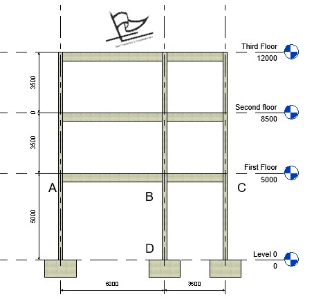
The column that shall be designed is column BD that has already been analysed for moment as part of a frame here. Since the column has already been evaluated to be subjected to a moment of 42.302KNm, we are left to evaluate the axial force acting on the column.
According to clause 3.8.2.3 of BS 8110, the axial force of a column in a structural frame may be calculated on the assumption that beams and slabs transmitting force into the particular column are simply supported. By this, the reaction from the column can be calculated which in turn serves as the load on the column. The axial force on the column BD is calculated below.
Computation of Axial load
For easy reference for axial load computation, the analyzed frame is reproduced below:
Third Floor Load take down
Characteristic permanent load on beam (gk) = 23KN/m
Characteristic variable load on beam (qk) = 36KN/m
Maximum ultimate Load acting on beam = 1.4(23) + 1.6(36) = 89.8KN/m
Load from third floor to column BD = (6/2 + 3.5/2) X 89.8 = 426.55
Second Floor and first floor Load take down
Characteristic permanent load on beam (gk) = 100KN/m
Characteristic variable load on beam (qk) = 40KN/m
Maximum ultimate Load acting on beam = 1.4(40) + 1.6(100) = 216KN/m
Load from second floor to column BD = (6/2 + 3.5/2) X 216 = 1026KN
Load from first floor to column BD = (6/2 + 3.5/2) X 216 = 1026KN
It should be noted that since we are computing for the axial load in this article, the maximum ultimate load is used all through as this gives the unfavorable axial load possible.
Axial Load on Column BD
The total axial load on the column is the summation of axial load from third, second, and first floors. This is done below:
Total Axial load on column BD = 426.55 + 1026 + 1026 = 2478.55KN
Steps in designing the column
Having calculated the axial load on the column, we can now proceed with the design of the column. However, before embarking on the proper design, let us write down the loads and other design parameters necessary for the column design.
Moment on the column (M) = 42.302KNm
Axial load on the column (N) = 2478.55KN
Length (l) = 5m
Breadth (b) = 250mm
Height (h) = 250mm
fck = 25N/mm2
cover = 25mm
-
Check the Slenderness of the column.
The slenderness ratio of the column shall be compared against the limiting slenderness, if the slenderness ratio is greater than the limiting slenderness then the column is declared “slender”. The column is declared “short” if otherwise. This is shown in the below steps
1. Calculate the effective height of the column
Since the column is braced, the Effective height (lo) is calculated thus:
le = β lo
a) Calculate the clear height (lo) of the column
In this example, we shall maintain the clear height to be the apparent height of the column which is 5m
b) Evaluate the relative stiffness at the column ends
β is a coefficient dependent on the end condition of the column. Its value can be obtained from table 3.19 and 3.20 of BS 8110-1:1997, however a rigorous approach will be adopted here according to clause 2.5 of BS 8110-2: 1985.
According to BS 8110 part 2, for braced column B is adopted as the lesser of:
β = 0.7 + 0.05(αc1 + αc2)
β = 0.85 + 0.05αcmin
αc2 and αc1 are the relative flexibilities of the top and bottom ends respectively
αc2 = $
\frac{\frac{\varSigma I_c}{l}}{\frac{\varSigma EI_b}{l}}
$
$
\frac{\frac{\frac{bh^3}{12}}{l}}{\frac{\frac{bh^3}{12}}{l}\,\,+\,\,\frac{\frac{bh^3}{12}}{l}}
$
$
\frac{\frac{\frac{250 X 250^3}{12}}{5000}}{\frac{\frac{225 X 500^3}{12}}{6000}\,\,+\,\,\frac{\frac{225 X 500^3}{12}}{3500}}
$
= 65104.2/(390625+ 669642.8)
= 0.06
We calculate for αc1
From clause 2.5.4 of BS 8110 part 2, the relative stiffness of a base designed to resist column moment is 1.0. This description above fits connection between the bottom end of the column and its base. Hence αc1 = 1.0
β = 0.7 + 0.05(1.0 + 0.06) = 0.753
β = 0.85 + 0.05 x 1.0 = 0.853
Since 0.753 is lesser than 0.853, hence β = 0.753
c. Determine the effective height
l = β lo
l = 0.753 x 5000 = 3765.53mm
2. Compare the slenderness ratio against the limiting slenderness.
lex/h and ley/b < 15 – braced column
lex/h = 3765.53/250 = 15.06
ley/b = 3765.53/250 = 15.06
Since lex/h and ley/b are not less than 15 then the column is slender and additional moment due to slenderness is required.
Check that the slenderness is within the slenderness limit.
The slenderness limit is that:
Lo ≤ 60b or 100b²/h, whichever is less
5000 ≤ 60 x 250
5000 ≤ 15000
Since lo is less 60b then the slenderness limit is satisfied
Calculate the additional moment (Madd) due to slenderness effect
Since the column is slender, additional moment due to slenderness is necessary.
Additional moment (Madd) = N X au
Calculate deflection due to slenderness
au= Ba KH
Ba = 1/2000 x (le/b)²
= 1/2000 x (3765.53/250)² = 0.113
K can be conservatively taken to be 1 (see clause 3.8.3.1 of the code)
au = 0.113 x 1 x 250 = 28.356
Madd = N X au
= 2478.55 x 28.356/1000 = 70.28KNm
. Compute the design moment (M)
The design moment is the greatest of:
- M2
2. Mi+ Madd
3. M1.+ Madd/2
We have excluded moment due to minimum eccentricity as this cannot be critical in a slender column. At least, the deflection due to slenderness is expected to be higher than the minimum eccentricity.
where: Mi = 0.4 M02 + 0.6 M01 = 25.38KNm
M2 = 42.302KN
Mi + Madd = 25.38 + 70.28 = 95.66KNm
M1 + Madd/2 = 0 + 70.28/2 = 35.14KNm
The design moment is 95.66KNm
Use the design Chart to determine the area of longitudinal reinforcement required
In order to use the design chart, few parameters have to be calculated
a. Determine N/bh
N/bh = 2478.55 x 10^3 /250 X 250 = 39.65
b. Determine M/bh²
M/bh² = 95.66 X 10^6/250 X 250² = 6.1
c. Calculate d/h
d/h determines the exact graph that shall be used to determine the reinforcement area.
d = h- c + ϕ/2 + ϕ
= 250 – 25 – 16/2 – 10 = 207mm
d/h = 207/250 = 0.8
The design chart with parameters which conforms with d/h = 0.9, fcu = 25N/mm2, and fy = 460N/mm2 is used. Chart No 22 in BS 8110 Part 3 matches this. The chart is reproduced below.
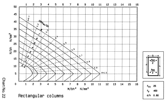
From the design chart, the intersection of M/bh² = 6.1 and N/bh = 39.6 falls outside the boundary of the curve. This means the load and moment acting on the column exceeds its capacity. To circumvent this, we shall increase the height of the column (h) to 350mm. By this the column cross-section becomes 250 x 350mm.
We re-determine the parameters
- Determine N/bh
N/bh = 2478.55 x 10^3 /250 x 350 = 28.3
- Determine M/bh²
M/bh² = 95.66 x 10^6/250 x 350² = 1.4
- Calculate d/h
d/h determines the exact graph that shall be used to determine the reinforcement area.
d = h – c – d – d/2
= 350 -25 – 10 – 16/2 = 307
d/h = 307/350 = 0.87
d/h is approximated to 0.9. This time around Chart No 24 is used. the intersection of M/bh² = 1.4 and N/bh = 28.3 falls on the 5.0 mark, this is shown with the red lines drawn on the chart as displayed below:
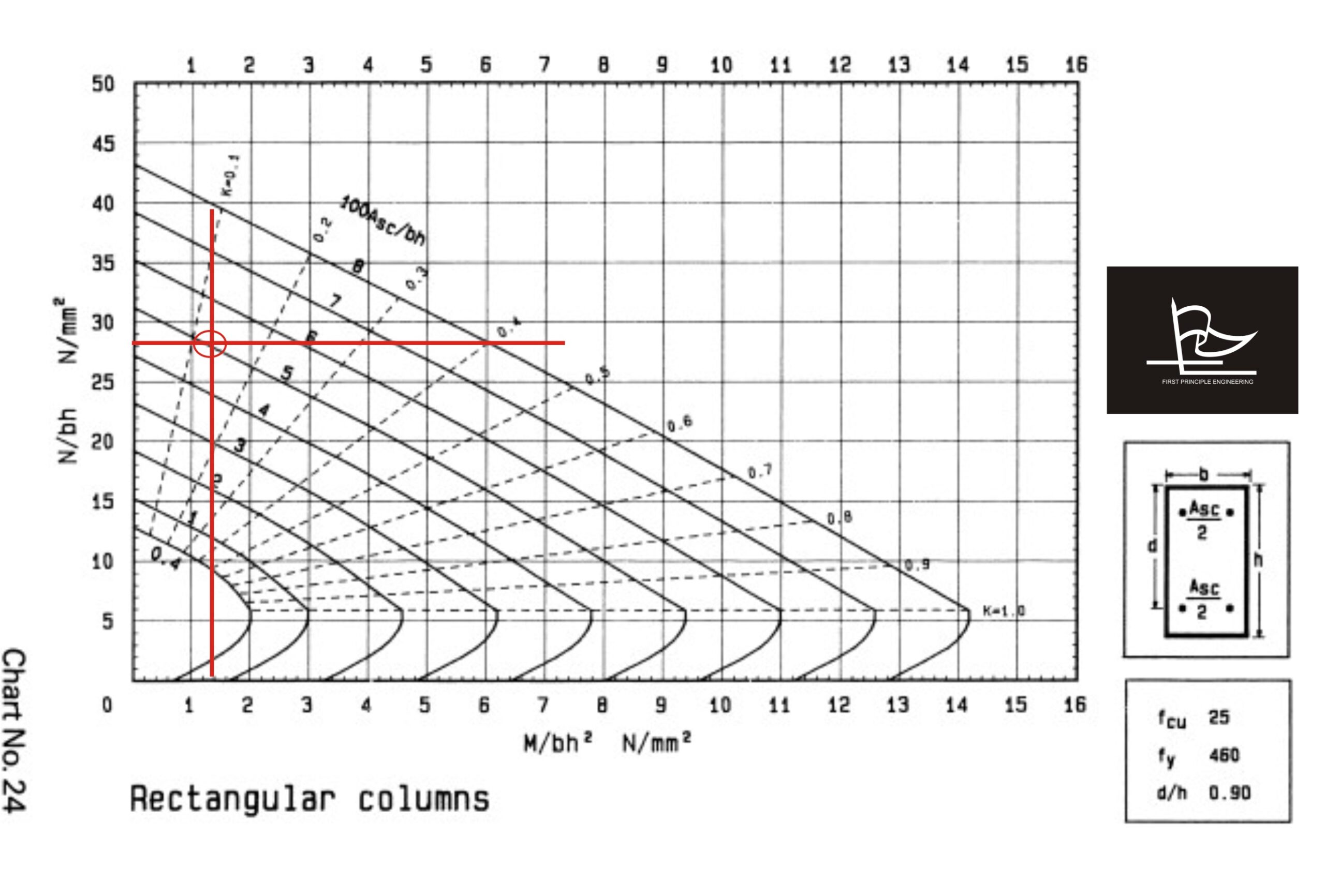
Hence from the design chart:
100Asc/bh = 5.0
Asc = 5.0 x 250 x 350/100
Asc= 4375mm²
Provide 9Y25 (4393mm²) as longitudinal bars.
-
Check minimum and maximum area of reinforcement requirement
From the design chart it is obvious the minimum and maximum area of reinforcement requirement are satisfied as the percentage area of reinforcement (100Asc/bh) is higher than the lower boundary 0.4 and lower than the upper boundary 6.0
(Note: The 8.0 limit on the design chart is meant for horizontally cast columns which is not what we have in this example)
ie: 0.4 ≤ 100Asc/bh ≤ 6.0
-
Determine the link diameter and spacing
- Link diameter
The link diameter is the greater of;
- ¼ x maximum diameter of longitudinal bar
- 6mm
¼ x maximum diameter of longitudinal bar = ¼ x 25 = 6.25mm
Hence use 10mm as the link diameter.
2. Link Spacing
The link spacing should be;
- 12 x minimum diameter of longitudinal bar
12 x minimum diameter of longitudinal bar = 12 x 25 = 300mm
Provide 10mm links at 250mm spacing.
Detailing
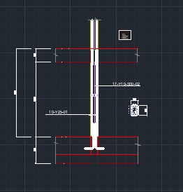
NB: For symmetry of the reinforcement, 10Y25 is provided rather than 9Y25 enumerated in the design.