This article presents a worked example on the design of doubly reinforced concrete beam to BS 8110
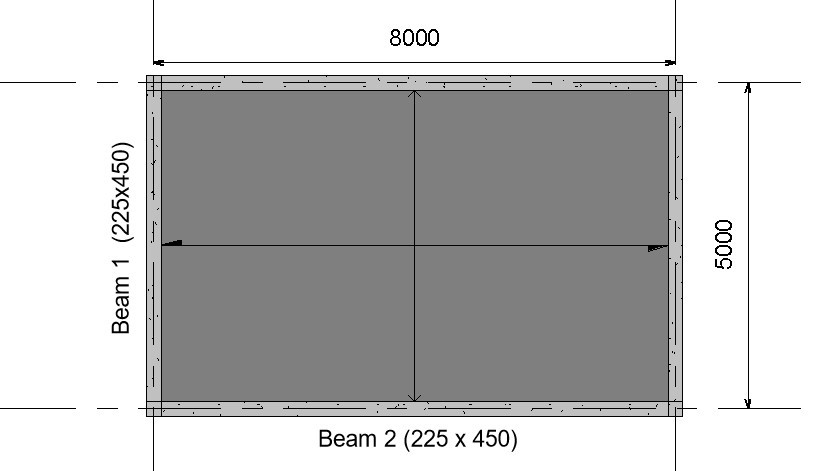
The image below shows the Plan view of a reinforced concrete structure, use the data given below to design Beam 2
Design Data:
Variable load on slab = 5KN/m2
Finishes = 1.5KN/m2
Unit weight of concrete = 24KN/m3
Compressive strength of concrete (fcu) = 25N/mm2
Characteristic Strength of main reinforcement (fy) = 460N/mm2
Characteristic Strength of Shear reinforcement (fyv) = 460N/mm2
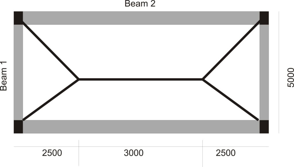
To design Beam 2, we will first distribute the slab loads on the beam and then analyze the beam to compute its internal forces. As shown in fig (2) below the tributary area of slab loads on beam 2 is a trapezium, hence we compute and distribute the slap loads on it as follows:
However, to understand the process of distributing slab load to beams in detail, read, “Distribution of Slab loads to beams.”
Analysis
Permanent Load
Characteristic Self-weight of slab = 0.2 x 24 = 4.8KN/m2
Partition Load on Slab = 1.5KN/m2
Characteristic Permanent Load on Slab = 4.8 + 1.5 = 6.38KN/m2
Area of Slab load Supported by Beam 2 = (0.5 x (8 + 3) x 2.5)/8 = 1.73m2
Permanent Load of Slab on Beam 2 = 1.72 x 6.38 = 10.97KN/m
Self-weight of beam = 0.23 x 0.45 x 24 = 2.48KN/m
Total Permanent Load on beam = 10.97 +2.48 = 13.5 KN/m
Variable Load
Variable load on slab = 5KN/m2
Area of Slab load Supported by Beam 2 = (0.5 x (8 + 3) x 2.5)/8 = 1.73m2
Characteristic Variable Load of Slab on Beam 2 = 1.258 x 5 = 8.59KN/m
Total Design Load
Ultimate Load acting on beam 2 = 1.4(13.5) + 1.6(8.59) = 32.3KN/m
Computation of Internal Forces:
The beam is assumed to be simply supported for ease of analysis.
M = w x L2/8 = 32.3 x 82/8 = 258.5KNm
V = W x L/2 = 32.3 x 8/2 = 129.24KN
Design
flexural strength design
- Calculate the effective depth
Assume 25mm diameter for cover
Assume main reinforcement to be 16mm
Shear reinforcement to be 10mm
Effective depth = h-c-link diameter-o/2
= 450-25-10-8
= 407mm
2) Check whether section is to be designed as singly or doubly reinforced beam
$
K\,=\,\,\frac{M}{bd^2f_{cu}}
$
$
K\,=\,\,\frac{258.5×10^6}{225×450^2×25}
$
= 0.3
Since K (0.3) > K’ (0.156); design as doubly reinforced.
3) Calculate the lever arm (Z)
$
Z\,\,=\,\,d\left( 0.5+\sqrt{\text{0.25}-\,\,\frac{K’}{0.9}} \right)
$
$
Z\,\,=\,\,407\left( 0.5+\sqrt{\text{0.25}-\,\,\frac{0.3}{0.9}} \right)
$
Since 333.4 < 0.95d (386.7): use Z = 316
4. Calculate the area of compression steel required.
$
As’\,\,=\,\,\frac{M\,\,-\,\,0.156fcubd^2}{0.87f_y\left( d\,\,-\,\,d’ \right)}
$
$
As’\,\,=\,\,\frac{258.5×10^6\,\,-\,\,0.156 x 25 x 225 x 407^2}{0.87 x 460\left( 407\,\,-\,\,43 \right)}
$
As’ = 711mm2
Provide 4Y16 (799.7mm2)
5. Calculate the area of tensile steel
$
As\,\,=\,\,\frac{K’fcubd^2}{0.87f_yZ}\,\,+\,\,Asc
$
$
As\,\,=\,\,\frac{0.156 x 25 x 225 x 407^2}{0.87 x 460 x 316}\,\,+\,\,799
$
As = 1859mm2
Provide 11Y16 (2199mm2)
NB: You will observe that the area of tension reinforcement is large, this can be attributed to the 8m long span of the beam, and more overriding, the assumption that the beam is simply supported which then result in large span moment.
Shear Strength Design
- Calculate the Shear Stress
- v = V/bd
- $\frac{129.24×10^3}{225×407}\,\,\,\,$
- = 1.4N/mm2
- $\frac{129.24×10^3}{225×407}\,\,\,\,$
- v = V/bd
- Check whether the concrete section can resist the shear force without shear reinforcement.
$
v_{c\,\,=}\,\,\text{0.79}\left( \frac{100As}{b_vd} \right) ^{\text{1/}3}\frac{\left( \frac{400}{d} \right) ^{\text{1/}4}}{\gamma _m}
$
$
v_{c\,\,=}\,\,\text{0.79}\left( \frac{100 x 1859}{225 x 407} \right) ^{\text{1/}3}\frac{\left( \frac{400}{407} \right) ^{\text{1/}4}}{1.5}
$
vc = 0.79N/mm2
Since vc(0.79) < v (1.4); Shear reinforcement is required.
3. Check the form of shear links to be provided according to table 3.7.
0.5vc = 0.5 x 0.79 = 0.4N/mm2
vc + 0.4 = 0.79 + 0.4 = 1.2 N/mm2
Since v > vc+0.4; shear links must be designed and the shear stress (v) must be checked not to be more than 0.8xfcu0.5 or 5N/mm2
0.8xfcu0.5 = 0.8 x 250.5 = 4.0N/mm2
Since v (1.4) is less than 0.8xfcu0.5 (4.0) then the beam section is adequate and shear reinforcement only needs to be designed.
4. Calculate the required minimum shear links.
Assume two-legged shear reinforcement of 10mm is to be used.
Area of 10mm shear reinforcement = 78.58mm2
Area of two-legged 10mm links = 2x 78.58 = 157mm2
$
Asv_{}=\,\,\frac{b_v\,\,x\,\,s_v\left( v-v_c \right)}{0.95fy_v}\,\,
$
$
Asv_{}=\,\,\frac{225\,\,x\,\,s_v\left( 1.4-0.79 \right)}{0.95 x 460}\,\,
$
Substituting 157mm2 for Asv and making sv the subject of the formular
sv = 497mm
5) Check whether maximum spacing limit is satisfied
Smax = 0.75xd
= 0.75 x 407
= 305mm
Since 497mm is greater than maximum spacing limit, maximum spacing limit governs the design.
Hence: provide Y10 @ 300mm spacing.
Deflection Check
Deflection Check
- Calculate the actual span-effective depth ratio
Span/depth ratio = 8000/407 = 19.7
2. Calculate the limiting Span-effective depth ratio
From table 3.9 of BS 8110, the basic Span/depth ratio for a simply supported beam is 20.
Tension reinforcement modification factor
$
\text{0.55}+\frac{477-\,\,f_s}{120\left( \text{0.9\,\,}+\,\,\frac{M}{bd^2} \right)}
$
where:
$
f_s\,\,=\,\,\frac{2f_yA_{sreq}}{3A_{sprov}}
$
$
f_s\,\,=\,\,\frac{2 x 460 x 1859}{3 x 2199 }
$
fs = 259.3
Substitute fs and values of other parameters into the tension modification formular
$
\text{0.55}+\frac{477-\,\,259.3}{120\left( \text{0.9\,\,}+\,\,\frac{258.5×10^6}{225 x 407^2} \right)}
$
= 0.78
Compression reinforcement modification factor
$
\frac{1+\frac{100Asprov}{bd}}{3+\frac{100Asprov}{bd}}
$
$
\frac{1+\frac{100 x 2199}{225 x 407}}{3+\frac{100 x 2199}{225 x 407}}
$
= 1.22
Modified basic span-effective depth ratio = basic span-effective depth ratio x M.F tension rebars x M.f compression rebars
Modified basic span-effective depth ratio = 20 x 0.78 x 1.22
= 19.15
Since Actual L/d (19.6) > modified Basic L/d (19.15); the beam fails deflection check.
viagra cost in india
Can you be more specific about the content of your article? After reading it, I still have some doubts. Hope you can help me.
Your point of view caught my eye and was very interesting. Thanks. I have a question for you.
Thanks for sharing. I read many of your blog posts, cool, your blog is very good.
Aut prodesse volunt aut delactare poetae — Поэты желают быть или полезными, или приятными.
Thanks for sharing your info. I really appreciate
your efforts and I will be waiting for your further
write ups thank you once again.
Hi there, You’ve done an excellent job. I will definitely digg
it and personally suggest to my friends.
I’m confident they will be benefited from this
site.
Howdy! Do you know if they make any plugins to assist with
SEO? I’m trying to get my blog to rank for some targeted keywords but I’m not seeing very good success.
If you know of any please share. Thank you!
Hmm is anyone else having problems with the images on this blog loading?
I’m trying to figure out if its a problem on my end or if it’s the blog.
Any responses would be greatly appreciated.
I don’t think the title of your article matches the content lol. Just kidding, mainly because I had some doubts after reading the article.
I visited multiple web pages however the audio feature for audio songs existing at
this site is actually marvelous.
medicijnen zonder voorschrift te koop Novartis Issy-les-Moulineaux
les médicaments acquièrent
Thanks for ones marvelous posting! I actually enjoyed reading it, you will be a great author.I will make sure to bookmark your blog and may come back down the road. I want to encourage you to continue your great writing, have a nice afternoon!
Pretty nice post. I just stumbled upon your blog and wished to say that I have really enjoyed browsing your blog posts. In any case I will be subscribing to your rss feed and I hope you write again very soon!