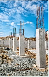
Columns are mostly used to transfer load from superstructure to foundation or to transfer members. Although they are primarily compression members, they are often times subjected to moment due to eccentricity of loading or asymmetrical arrangement of supported beams. When a column is susceptible to moment, the critical design case is to arrange the loads in patterns that will generate maximum moment and axial load in the column.
Braced and Unbraced Column
To effectively design a column, the ability to discern whether the column is braced or unbraced is paramount.
A column is said to be braced in a plane when it does not resist lateral loads or provide lateral stability in that plane as this are meant to be resisted by braces, shear walls, core walls, or other lateral load resisting elements incorporated in the structure.
An unbraced column on the other hand is meant to give lateral stability to the structure in the plane under consideration.
Effective height of column
The degree of fixity or the type of constraints at each end of a column is also very important to the overall resistance of the column. Accommodating the effect of this end conditions brought about the concept of effective height of column. BS 8110:2-1985 gives several formulas to determine the effective height of columns – whether braced or unbraced. These formulas are rigorous but much more accurate as it considers the relative stiffness of the column to the beams framing into it. BS 8110:1-1997, however, provides a simplified approach to determining the effective height through the formula below:
le= βlo
lo is the clear height of the column.
β is a function of the columns end conditions. Its value can be obtained from table 3.19 and 3.20 for braced and unbraced conditions respectively. To use the table, the end condition of one end of the column will be checked against the end condition of the other end to pick a value that is common to both ends. The code groups the end conditions of columns into four classes which are reproduced below
Condition 1. The end of the column is connected monolithically to beams on either side which are at least as deep as the overall dimension of the column in the plane considered. Where the column is connected to a foundation structure, this should be of a form specifically designed to carry moment.
ie: d ≥ h

Condition 2. The end of the column is connected monolithically to beams or slabs on either side which are shallower than the overall dimension of the column in the plane considered.
ie: d < h

Condition 3. The end of the column is connected to members which, while not specifically designed to provide restraint to rotation of the column will, nevertheless, provide some nominal restraint.
ie: d < h

Condition 4. The end of the column is unrestrained against both lateral movement and rotation (e.g. the free end of a cantilever column in an unbraced structure).
ie: d = o

The effective height of a column is very important that it is a factor that determines the slenderness of the column or the susceptibility of the column to buckling. In designing against buckling, the code categorizes columns into two:
- Short Column
- Slender Column
Short and Slender Column
According to BS 8110:1:1997, a short column is that which as lex/h and ley/b to be less than 15 when it is braced, otherwise it is slender. While an unbraced column is short when lex/h and ley/b are less than 10, otherwise it is slender.
i.e: lex/h and ley/b < 10 (unbraced column)
lex/h and ley/b < 15 (braced column)
Where: lex/h and ley/b are effective length relative to x and y axis respectively.
When a column is slender, besides the design moment caused by gravity and lateral loads, an additional moment (Madd) has to be catered for. This additional moment is the moment induced by deflection of the slender column.
The additional moment can be computed using:
Madd = Nau
Where;
N is the axial load on the column
au is the deflection of the column
Critical Design Moment in columns
In order to clearly categorize columns based on the computation of the design moment that will be adopted in sizing them assuming the moment is about a single axis, columns are better categorize into three, which are:
- Short column
- Braced Slender column
- Unbraced Slender Column
Short Column
The design of a short column is independent on whether it is braced or unbraced. Short columns are likely to fail by crushing so the axial load on them is always preponderance. We will only check the largest moment acting on it (M2 ) against the minimum moment prescribed by the code and adopt that which is greater.
Hence, the design moment to be adopted in designing a short column should be the larger of:
- M2
- emin x N.
Click here to study a worked example on the design of short column to BS 8110
Braced Slender Column
If a column is braced and bent about a single axis, the design moment to be adopted in design is the largest of:
a) M2
b) Mi+ Madd
c) M1 + Madd/2
d) emin x N
Mi is the initial moment which is given by the equation:
Mi = 0.4M1 + 0.6M2 ≥ 0.4M2
M1 and M2 are the small and large moment in the column assuming the column is bent about a double curvature.
emin is the minimum eccentricity. When a column is concentrically loaded such that only axial forces are acting on it, it has to be designed for a nominal moment which is obtained by multiplying the ultimate axial load by minimum eccentricity stipulated by the code. The minimum eccentricity is 0.05 x depth of the column in the plane being considered. The minimum eccentricity must not be more than 20mm.
The above equations will be applicable to slender column only when le/h is less than 20 and the ratio of its longer side to its shorter side is less than 3, when the column does not satisfy this then it should be designed as biaxial column.

Click here to study a worked example on the design of braced slender column to BS 8110
Unbraced Slender Column
If a column is unbraced, the critical design moment is obtained by adding the additional moment to the moments at the column ends. This is however a convenient simplification. Clause 3.8.3.7 of BS8110 part 1 stipulates that the additional moment is assumed to occur at whichever of the column end has the stiffer joint, and then the additional moment at the other end may be reduced in proportion to the ratio of the
joint stiffnesses at either end. This is depicted in the fig below which is extracted from the code

Column Subjected to biaxial bending
As it is often the case in practical sense, columns are subjected to moments, at least due to eccentricity, about both axes. In such a case of biaxial bending, the code permits that such columns may be designed to withstand an increased moment about one axis. The axis with which the moment will be increased is determined as follows:
If Mx/h’ ≥ My/b’ then the increased moment will be about x axis. The increased moment should be calculated thus: Mx‘ = Mx + β h’/b’ My
If Mx/h’ ≤ My/b’ then the increased moment will be about y axis. The increased moment should be calculated thus: My‘ = My + β h’/b’ Mx
Click here to study a worked example of the design of a Column subjected to biaxial bending.
Design of Columns
In most regular columns, serviceability criteria such as deflection and cracking are not critical so the columns are mostly designed for Ultimate Limit State of strength.
Since there is no design implication to whether a short column is braced or unbraced as they are always largely subjected to axial load and fail by crushing, the code stipulates increased axial capacity of short columns under two conditions:
- Short column subjected to axial load and nominal moment due to eccentricity
Columns with predominantly axial loads occur in braced structure and non-continuous member supporting symmetrical load or a very rigid member such as deep beams. Although the load on the column is predominantly axial, there is still tolerance for imperfection so the column is also designed for nominal moment.
For such a column the below formula is employed to design the area of reinforcement and determine the appropriate size of the column.
N = 0.4fcuAc + 0.8Ascfy
Where: N = Axial load
Ac = Area of column section
2. Short braced columns supporting an approximately symmetrical arrangement of beams
For a column to be considered as declared above, it has to satisfy two conditions:
- The loads on the beams are uniformly distributed
- The beam spans do not differ by more than 15% of the longer.
The moment on the column in this instance are due to asymmetrical arrangement of live load and are usually small. The ultimate load that can be supported by such a column should be derived from:
N = 0.35fcuAc + 0.7Ascfy
Columns resisting axial load and significant moment
The design of section subjected to both axial and bending moment is an extensive topic. There are different devised methods that can be used some of which are listed below:
- Approximate equations
- Design Chart given in BS 8110:3-1985
- Using M-N Interaction Diagram.
Reinforcement Detailing
- A minimum of four bars is required in a rectangular column while a minimum of six bars is required in a circular column
- The minimum percentage of steel (100As/Acol) is 0.4
- The maximum percentage of steel (100As/Acol) is 6.0 for vertical column while 8.0 for horizontal column.
- Minimum size of links equal 0.25 x the diameter of the compression reinforcement but not less than 6mm
- Every main bar in a corner should be firmly held by a link and any other bar not restrained by a link should be within 150mm of a restrained bar.
- Maximum spacing should not be greater than smallest longitudinal bars x 20
Reference(s)


ovodewa