A biaxial column is that which is subjected to moment about the two orthogonal axes. These types of columns are particularly found as corner columns in building structures. They are generally found in frame structures where columns support beams with unequal span along both planes of the columns. This article presents a worked example on the design of biaxial column to BS 8110 using design chart in part 3 of BS 8110. The column to be designed shall be taken from a 3D building analysis using Protostructure software.
Worked Example
The column is a upper storey, 250 by 250 column which is supported on a transfer beam. The transfer beam which spans along direction 2 is the only beam restraining the bottom end of the column, however the top end of the column is supporting two beams in both orthogonal directions (direction 1 and direction 2) as shown in the figure below.
Below is the data extracted from the software’s post-processing after analysis of the building.
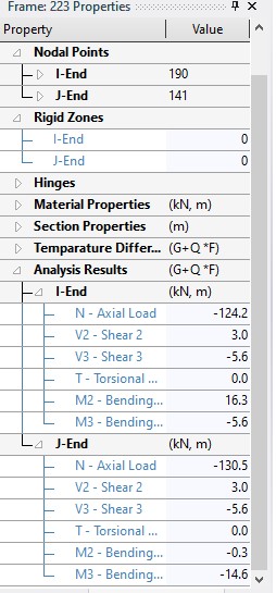
The design parameters extracted from post-processing are enumerated below:
Column dimension = 250 x 250mm
Moment at the top (Direction 1) = 16.3KNm
Moment at the top (Direction 2) = -5.6KNm
Moment at the bottom (Direction 1) = – 0.3KNm
Moment at the bottom (Direction 2) = -14.6KNm
Axial load (N) = 130.5KN
Compressive strength of concrete (fcu) = 25N/mm²
Tensile strength of steel (fy) = 460N/mm²
Cover = 25mm
Assume diameter of links = 10mm
Assume diameter of main reinforcement = 16mm
Steps in designing the Column
Each of the steps shall be applied to each direction of the columns in turn.
-
Check the Slenderness of the column.
The slenderness ratio of the column shall be compared against the limiting slenderness, if the slenderness ratio is greater than the limiting slenderness then the column is declared “slender”. The column is declared “short” if otherwise. This is shown in the below steps.
-
Calculate the effective height of the column
Since the column is braced, the Effective length (lo) is calculated thus: le = ßlo
a ) Calculate the clear height (lo) of the column in each direction
Direction 1
lo = clear height of column = 3000 – 450 x 0.5 = 2775mm
Direction 2
lo = clear height of column = 3000 – 450 x 0.5 – 450 x 0.5 = 2550smm
b) Evaluate the relative stiffness at the column ends (αc1 and αc2 ) in each direction.
αc1 and αc2 are the relative flexibilities of the top and bottom ends respectively. These are calculated in accordance to clause 2.5 of BS 8110-2: 1985.
Direction 1
αc2 = $ \frac{\frac{\varSigma I_c}{l}}{\frac{\varSigma EI_b}{l}} $
$ \frac{\frac{\frac{bh^3}{12}}{l}}{\frac{\frac{bh^3}{12}}{l}} $
$ \frac{\frac{\frac{250 X 250^3}{12}}{2775}}{\frac{\frac{225 X 450^3}{12}}{6000}} $
= 117304.8/284765.6 = 0.412
Since there is no beam framing into the column along that direction (Direction 1), we assume the beam is simply supported and only supporting nominal moment. Hence according to clause 2.5.4 in part 3 of BS8110 αc1 = 5
Direction 2
αc2 = $ \frac{\frac{\varSigma I_c}{l}}{\frac{\varSigma EI_b}{l}} $
$ \frac{\frac{\frac{bh^3}{12}}{l}}{\frac{\frac{bh^3}{12}}{l}} $
$ \frac{\frac{\frac{250 X 250^3}{12}}{2550}}{\frac{\frac{225 X 450^3}{12}}{6000}} $
= 127655.2/284765.6 = 0.448
αc1 = $ \frac{\frac{\varSigma I_c}{l}}{\frac{\varSigma EI_b}{l}} $
$ \frac{\frac{\frac{bh^3}{12}}{l}}{\frac{\frac{bh^3}{12}}{l}} $
$ \frac{\frac{\frac{250 X 250^3}{12}}{2550}}{\frac{\frac{225 X 450^3}{12}}{6000}} $
= 127655.2/284765.6 = 0.448
c) Determine the value of B in each direction
According to BS 8110 part 2, for braced column B is adopted as the lesser of:
β = 0.7 + 0.05(αc1 + αc2)
β = 0.85 + 0.05αcmin
Direction 1
B = 0.7 + 0.05(0.412 + 5) = 0.971
B = 0.85 + 0.05 x 0.412 = 0.871
B = 0.871
Direction 2
B = 0.7 + 0.05(0.448 + 0.448) = 0.740
B = 0.85 + 0.05 x 0.448 = 0.868
B = 0.740
d) Determine the effective height
Direction 1
l = 2775 x 0.871 = 2415.9
Direction 2
l = 2550 x 0.740 = 1886.8
2. Compare the slenderness ratio against the limiting slenderness.
lex/h and ley/b < 15 – braced column
Direction 1
lex/h = 2415.9/250 = 9.664
ley/b = 2415.9/250 = 9.664
Since lex/h and ley/b are less than 15 then the column is short and additional moment due to slenderness is not required.
Direction 2
lex/h = 1886.8/250 = 7.55
ley/b = 1886.8/250 = 7.55
Conclusion: Since lex/h and ley/b are less than 15 then the column is short and additional moment due to slenderness is not required.
-
Compute the design moment (M)
The design moment is the greater between M2 and N x emin
Since the column is square (250mm X 250mm) in cross-section, the minimum moment related to each direction is the same.
Minimum moment is N x emin
emin (the minimum eccentricity) = 0.05 X h (>= 20mm)
emin = 0.05 x 250 = 12.5mm
Since 12.5mm is not greater than 20mm, the minimum eccentricity is taken as 12.5mm
Minimum moment = (12.5/1000) X 130.5 = 1.63KNm
Since the minimum moment is less than M2 (the greater of the end moments of the column) in both direction, hence the critical moment to be adopted for the design is 16.3KNm and 14.6KNm in direction 1 and direction 2 respectively.
-
Compute the equivalent moment about a single axis.
If Mx/h’ ≥ My/b’ then Mx‘ = Mx + β h’/b’ My
If Mx/h’ ≤ My/b’ then My‘ = My + β h’/b’ Mx
Mx/h’ = 16.3/207 = 0.079
My/b’ = 14.6/207 = 0.070
Since Mx/h’ ≥ My/b’ then the equivalent uniaxial moment is calculated thus: Mx‘ = Mx + β h’/b’ My
N/bhfcu = 130.5 X 10^3/250 x 250 x 25 = 0.084 = 0.1
Check for value of β corresponding to 0.1 in table 3.22 of BS 8110
β = 0.88
Mx‘ = 16.3 + 0.88 ( 207/207 ) 14.6 = 29.148KNm
-
Use the design Chart to determine the area of reinforcement required
In order to use the design chart, few parameters have to be calculated;
1. Determine N/bhfcu
N/bhfcu = 130.5 X 10^3/250 x 250 x 25 = 0.084 = 0.1
2. Determine M/bh²fcu
M/bh²fcu = 29.148 X 10^6/250 X 250² X 25 = 0.075
3. Calculate d/h
d/h determines the exact graph that shall be used to determine the reinforcement area
d = h- c + ϕ/2 + ϕ
= 250 – 25 – 10 – 8 = 207
d/h = 207/250 = 0.8
The design chart with parameters which conforms with d/h = 0.8, fcu = 25N/mm2, and fy = 460N/mm2 will be used. Chart 22 in BS 8110 Part 3 matches this. The chart is reproduced below.
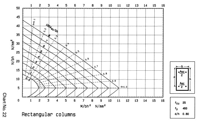
From the design chart, the intersection of M/bh2fck = 0.075 and N/bhfck = 0.1 falls below the 0.4 mark. This implies there is no need to provide reinforcement for the column. However, to keep to BS 8110 directives minimum area of reinforcement shall be provided.
minimum reinforcement (Asmin) = 100As/Acol = 0.4 Asmin
= 0.004 X 250 X 250 Asmin = 250mm2
Provide 4Y12 (449.856mm2) as the longitudinal reinforcement of the column
-
Determine the link diameter and spacing
-
Link diameter
The link diameter is the greater of;
- ¼ x maximum diameter of longitudinal bar
- 6mm
¼ x maximum diameter of longitudinal bar = ¼ x 12 = 3mm
Hence use 6mm diameter bar as links.
2. Link Spacing
The link spacing should not be greater than 12 x minimum diameter of longitudinal bar
- 12 x minimum diameter of longitudinal bar = 12 x 12 = 144mm
Provide 6mm links at 125mm spacing.