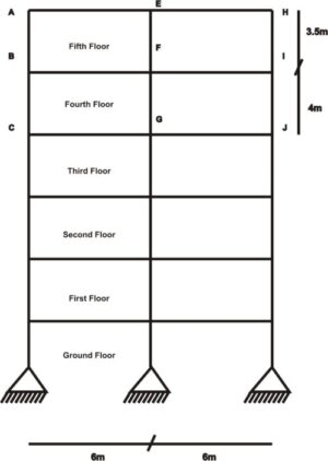
In this article, we shall analyze a subframe to generate column moments using moment distribution methodmoment distribution method. The figure below shows the elevation view of a frame structure. A subframe extracted from this whole frame shall be analysed to obtain the moment in column BD.
Steps in evaluating moment in column BD
Step 1: Draw the ideal Subframe.
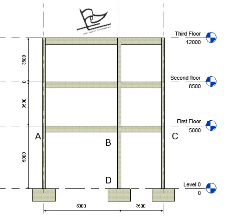
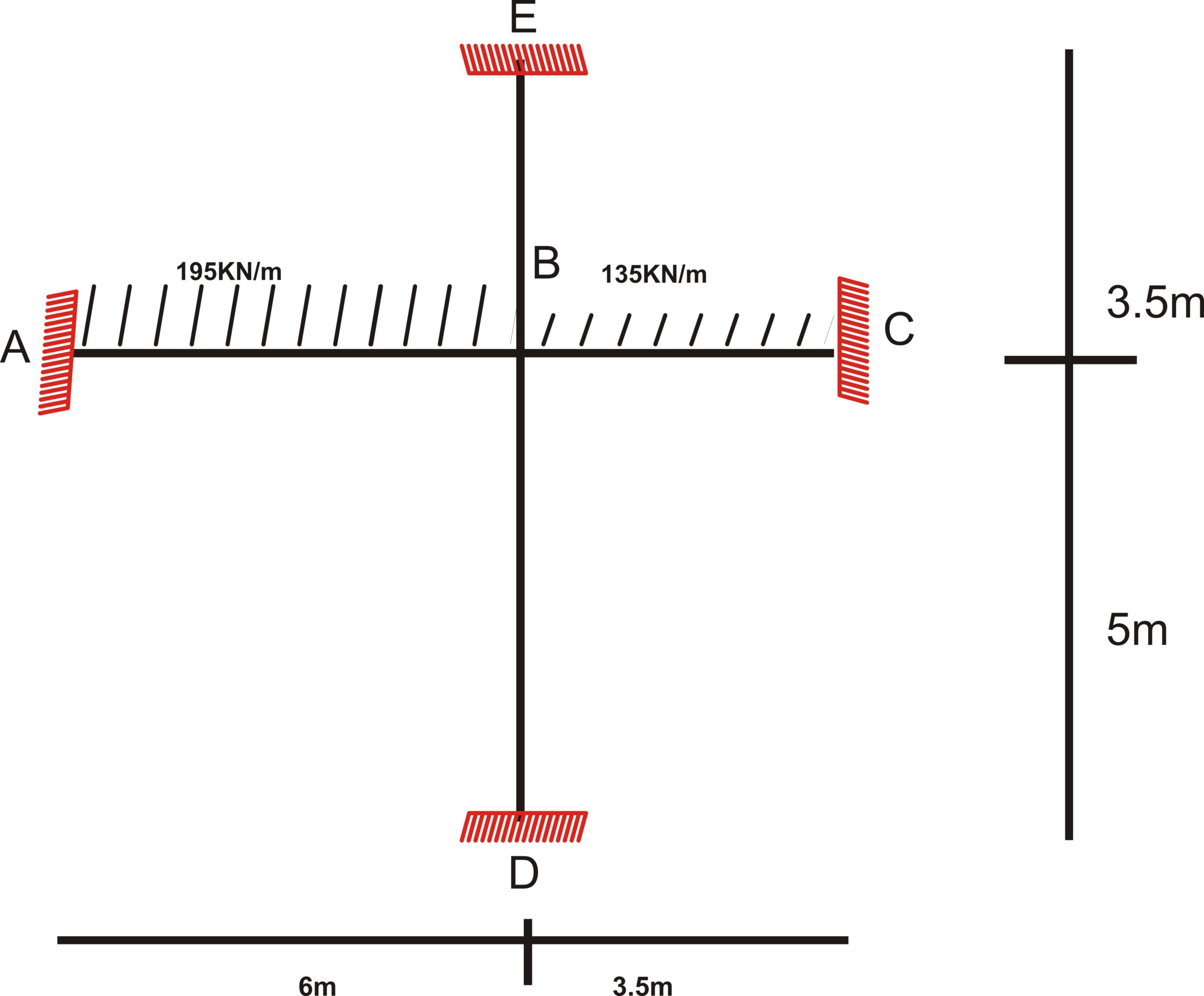
The first step to analyzing column BD is to draw out the most suitable subframe that requires the least computation to determine the column moment. This subframe is that which will include the whole beam span connected to column BD and the adjoining upper column as shown below.
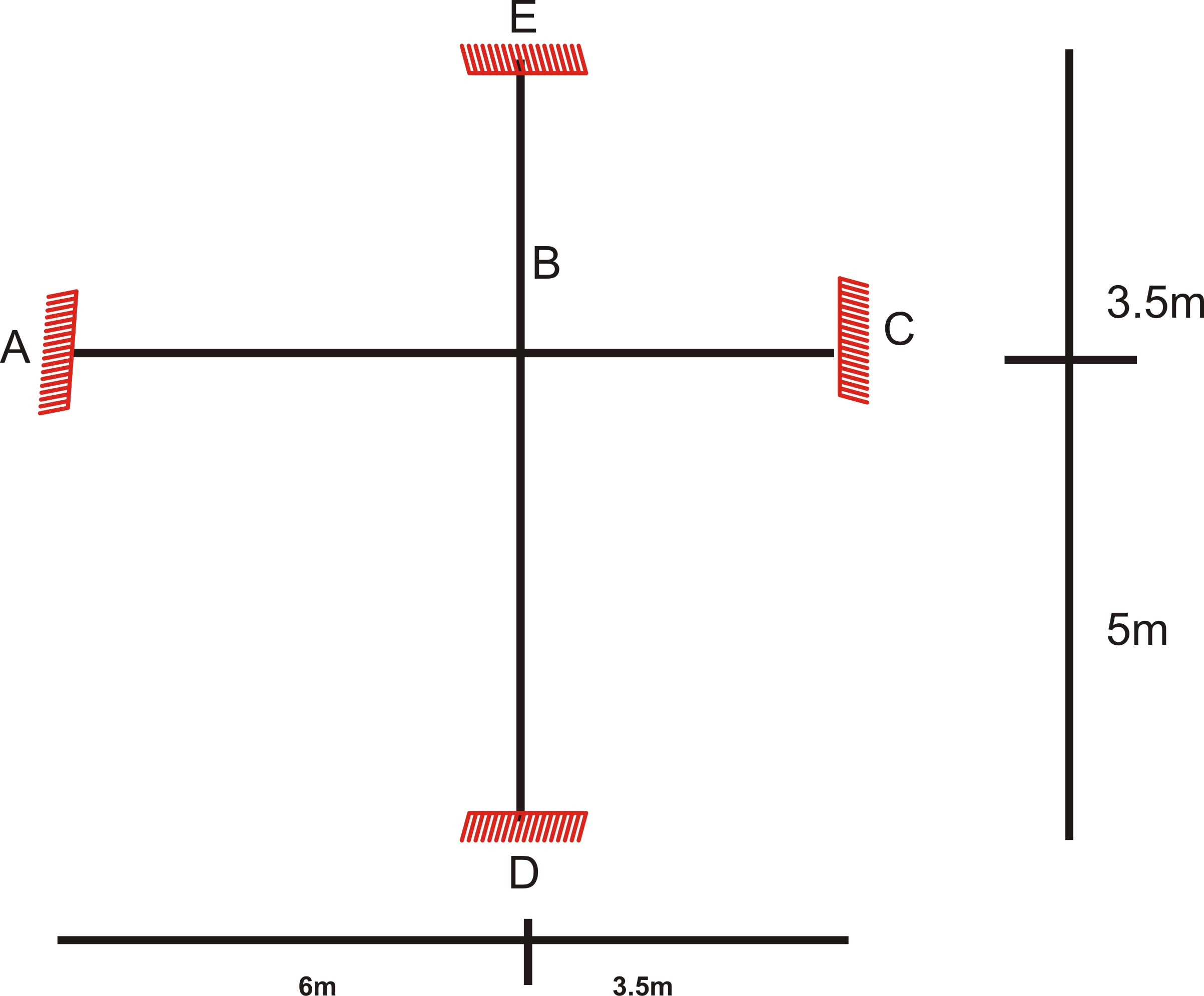
Since we have clearly extracted the subframe, let us write out the member dimensions.
Members dimensions
Column BD: Length = 5m, Cross Section = 250 x 250 mm
Column BE: Length = 3.5m, Cross Section = 250 x 250 mm
Beam AB: Length = 6m, Cross Section = 225 x 500mm
Beam BC: Length = 3.5m, Cross Section = 225 x 500mm
Step 2: Compute the ultimate loads acting on the beams.
In order obtain the maximum possible moment on column BD, the maximum ultimate load and the minimum ultimate load shall me made to act on beam AB and BC respectively. This will create the most unfavorable moment possible in column BD.
Characteristic permanent load on beam (gk) = 100KN/m
Characteristic variable load on beam (qk) = 40KN/m
Maximum ultimate Load acting on beam = 1.35(40) + 1.5(100) = 195KN/m
Minimum ultimate Load acting on Slab = 1.35(100) = 135KN/m
The load is applied on the subframe as shown in the diagram below.
Step 3: Assume every support in the beam is fixed and calculate the fixed end moment of the beams.
Thus:
$ _{M_{AB\,\,}}\,\,=\,\,-\,\,\frac{w\,\,*\,\,\begin{array}{l} L²\\ \end{array}}{12} $ = $\frac{-195\,\,*\,\,\begin{array}{l} 6²\\ \end{array}}{12} $ = -585KNm
$ _{M_{BA\,\,}}\,\,=\,\,\frac{w\,\,*\,\,\begin{array}{l} L²\\ \end{array}}{12} $ = $\frac{195\,\,*\,\,\begin{array}{l} 6²\\ \end{array}}{12} $ = 585KNm
$ _{M_{BC\,\,}}\,\,=\,\,-\,\,\frac{w\,\,*\,\,\begin{array}{l} L²\\ \end{array}}{12} $ = $\frac{-135\,\,*\,\,\begin{array}{l} 3.5²\\ \end{array}}{12} $ = -137.8
$ _{M_{CB\,\,}}\,\,=\,\,\frac{w\,\,*\,\,\begin{array}{l} L²\\ \end{array}}{12} $ = $\frac{135\,\,*\,\,\begin{array}{l} 3.5²\\ \end{array}}{12} $ = 137.8
Step 4: Determine the stiffness of each member
The Stiffness of each member is determined. The columns and the beams have the same cross-section respectively, hence the second moment area of all the columns are the same, and that of all the beams are also equal.
For the columns: I = bh³/12 = (0.25 x 0.25³)/ 12 = 0.002
For the beams: I = bh³/12 = (0.25 x 0.5³)/12 = 0.005
The stiffness of each member is 4EI/L. However, the stiffness of the connecting beams is halved as it is assumed that considering the far ends of those beams as fixed in the subframe will lead to exaggeration of their stiffnesses.
$ _{K_{AB\,\,}}$ = 1/2 * 4EI/L = (0.5 x 4 x 0.005 x E )/6 = 0.0008E
$ _{K_{BC\,\,}}$ = 1/2 * 4EI/L = (0.5 x 4 x 0.002 x E )/3.5 = 0.0013E
$ _{K_{BD\,\,}}$ = 4EI/L = (4 x 0.0003 x E )/5 = 0.0003E
$ _{K_{BE\,\,}}$ = 4EI/L = (4 x 0.0003 x E )/3.5 = 0.0004E
Step 4: Determine the distribution factor
$ DF_{AB}\,\,=\,\,\,\,\frac{K_{AB}}{K_{AB}\,\,+\,\,K_{BC}\,\,+\,\,K_{BD}\,\,+K_{BE}\,\,}\,\,=\,\,\frac{0.0008E}{0.0008E\,\,+\,\,0.0013E\,\,+\,\,0.0003E\,\,+0.0004E\,\,\,\,}\,\,=\,\,0.284 $
$ DF_{BC}\,\,=\,\,\,\,\frac{K_{BC}}{K_{AB}\,\,+\,\,K_{BC}\,\,+\,\,K_{BD}\,\,+K_{BE}\,\,}\,\,=\,\,\frac{0.0013E}{0.0008E\,\,+\,\,0.0013E\,\,+\,\,0.0003E\,\,+0.0004E\,\,\,\,}\,\,=\,\,0.486 $
$ DF_{BD}\,\,=\,\,\,\,\frac{K_{BD}}{K_{AB}\,\,+\,\,K_{BC}\,\,+\,\,K_{BD}\,\,+K_{BE}\,\,}\,\,=\,\,\frac{0.0003E}{0.0008E\,\,+\,\,0.0013E\,\,+\,\,0.0003E\,\,+0.0004E\,\,\,\,}\,\,=\,\,0.095 $
$ DF_{BE}\,\,=\,\,\,\,\frac{K_{BE}}{K_{AB}\,\,+\,\,K_{BC}\,\,+\,\,K_{BD}\,\,+K_{BE}\,\,}\,\,=\,\,\frac{0.0004E}{0.0008E\,\,+\,\,0.0013E\,\,+\,\,0.0003E\,\,+0.0004E\,\,\,\,}\,\,=\,\,0.135 $
In order to make our iteration concise and tidy when making the moment distribution operations, it is a good practice to group columns meeting at a joint together. To implement this, we add together the distribution factors of the two columns meeting at a joint so that the columns can be treated as a single member.
DFBD + DFBE = 0.095 + 0.135 = 0.23
Step 5: Enter the values of the fixed end moment and distribution factor in a table and initiate subsequent iterations
The values of fixed end moment and Distribution factors are entered in a table as shown below. The out of Balance Moment (OBM) is then calculated, then also is the carry-over moment like that of any other moment-distribution operation. If the operations are diligently carried out, the result should be as that as shown below:
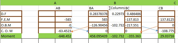
The moment of column BD can be gotten by multiplying the overall moment of the two columns meeting at that particular joint by the distribution factor of column BD. This is carried out below:
$ M_{BD}\,\,=\,\,\text{102.732,}X\,\,\frac{K_{BD}}{K_{BD}\,\,+\,\,K_{BE}}\,\,=\,\,\text{102.732,}X\,\,\frac{0.0003}{\text{0.0003}+\,\,0.0004}\,\,=\,\,42.302KNm $