
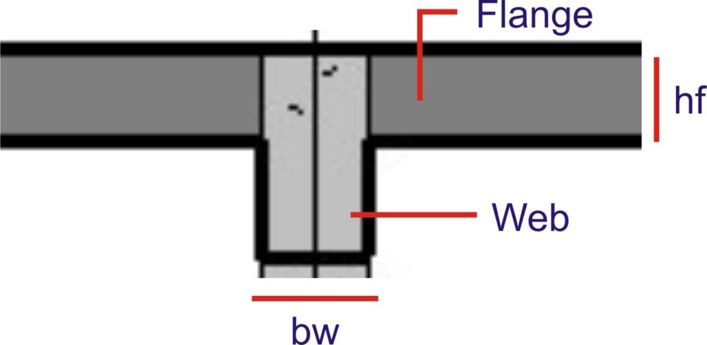
A flange section is that which has a rectangular extension from the main rectangular body. The extension is called a flange while the rectangular body is called web. This type of section mostly occurs when a beam is cast monolithically with a slab.
The design of flange beam is similar to that of rectangular section only that the flange gives additional area of concrete which adds to the overall compressive strength of the section. So instead of using the breadth of the rectangular section only in estimating the compressive strength of the section, the breath of the rectangular section plus that of the flange is used thereby augmenting the compressive strength of the beam.
It is however very pertinent to note that this increase in compressive strength due to the flange area will be valid only when the flange is in compression. Whenever the flange is in tension, the section should be designed as a rectangular beam as more concrete area in tension will actually serve little or no purpose.
Types of Flange Section
Flange sections are however categorized based on their geometry. The two basic types are:
- L section
- T section
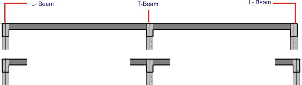
The L sections are mostly found in perimeter beams of building as the slab is only spanning from the beam on one side while the T section on the other hand is mostly found in buildings intermediate beams as slabs span from both sides of the beam.
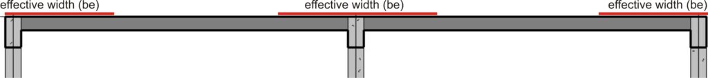
EFFECTIVE WIDTH OF FLANGE
When the flange of a beam is exploited in designing a beam, the total span of the adjoining slab when large does not often act with the supporting beam to resist the loads on the beam, only some portion of the slab does. To calculate the portion of the slab that act together with the beam to resist loads results to the concept of effective width of flange.
The effective width of flange according to BS 8110 is stipulated below
For L section: web width + (whichever is smaller between) Lz/10 or actual flange width
For T section: web width + (whichever is smaller between) Lz/5 or actual flange width
Where Lz is defined as the distance between point where moment is zero. This can be taken as the entire span for a simply supported beam. As for a continuous beam Lz should be taken as 0.7x times the effective span of the beam.
Flexural design of Flange Beams
For the design of a flange in flexure, two cases are paramount to be considered:
- When the portion of concrete to resist compression lies within the flange (ie: Neutal axis lies within the flange)
- When the portion of concrete to resist compression extends beyond the flange.(ie: Neutral axis lies below the flange)
When Neutral axis lies within the Flange
In designing a flange section, when the area of concrete within the flange section is enough to develop the strength required to resist the compressive force, then the beam is designed as a rectangular section with breath bf (effective flange width). Therefore, the moment of resistance of the section can be calculated using:
Mu = Kbfd2fcu (k = 0.156)
When Mu < M, then the stress block is truly within the flange and the beam is designed as singly reinforced.
The area of tensile reinforcement in this case can be determined using:
$A_{s\,\,=\,\,\frac{M}{0.87f_yZ}}
$
When Neutral axis lies below the Flange
However, when the stress block to resist compressive force extends below the flange, then these can be designed by either
- Calculating the exact depth of the web below the flange that is harnessed to resist the compressive force.
- By conservatively assuming that the depth of the neutral axis of the section equals half of the effective depth of the beam section.
To calculate the actual depth of the web that partakes in resisting compression can be very tedious, as a work around, and in conformance with the formula given in BS 8110, the author prefers conservatively taking the depth of the neutral axis to be half of the effective depth.
Consequently, the moment of resistance of the section will be the moment of resistance of the flange plus the moment of resistance of the web.
ie: Mu = Mf + Mw
0.45fcu(bf – bw)(d – hf/2)hf + 0.156fcubd2
If the design moment (M) is greater than the moment obtained after evaluating the above formula, then the section shall be designed as doubly reinforced.
BS 8110:1:1997 gives the formula for calculating the area of tensile reinforcement when the neutral axis falls below the flange as:
$
A_s\,\,=\,\,\frac{M\,\,+\,\,0.1f_{cu}b_wd\left( 0.45d\,\,-\,\,h_f \right)}{0.95f_y\left( d\,\,-\,\,0.5h_f \right)}
$
Longitudinal Shear Design
There is always a shear at the connection between the web and the flange. The code, in table 3.25, stipulates that minimum area of steel of 0.15% of reinforcement should be provided over full effective flange width to resist horizontal shear.
Vertical Shear Design
The design of shear force for flange beam is exactly the same for a rectangular beam except that the breadth of the flange beam, (bv) is always taken as the breadth of the rib below the flange.
As in the case of rectangular beams, the shear stress (v) is checked against the shear strength of the concrete (vc). The shear stress (v) is calculated by dividing the shear force (V) in the section by the effective cross-section area of the section.
ie: v = V/bd
The shear strength (vc) of the concrete section is affected by a few numbers of variables. The strength of the concrete is a chief factor, likewise do the interlocking action and dowel action of the coarse aggregate and longitudinal reinforcement bars respectively contribute also considerably. This can be observed in table 3.8 of the code where the percentage longitudinal reinforcement is to be checked against the effective depth of the concrete section to obtain the shear strength of the section.
So when the shear stress (v) is lesser than the shear strength (vc) plus 0.4N/mm2 minimum links is to be used.
i.e.: if v < Vc + 0.4 – Asvmin
where:
$
Asv_{\min}=\,\,\frac{\text{0.4}x\,\,b_v\,\,x\,\,s_v}{0.9fy_v}\,\,
$
However, if the shear stress (v) is greater than Vc + 0.4 then the shear reinforcement should be designed for using:
$
Asv_{}=\,\,\frac{b_v\,\,x\,\,s_v\left( v-v_c \right)}{0.95fy_v}\,\,
$
t is nonetheless pertinent to note that on no account should the shear stress be greater than the lesser of 5N and 0.8xfcu0.5 should this happen then the section must be resized and redesigned.
When the shear stress is extremely low such that it is lesser than half of the concrete shear strength as it happens in lightly loaded element such as lintel, the shear links should not be provided theoretically. However, for all practical purpose, it is pragmatic to provide minimum links so that a reinforcement cage can be formed and large cracks can be prevented.
Under no circumstances should the spacing of the links exceed 0.75d. And at right-angles to the span, the spacings of the main tension bar should be within 150 mm from a vertical leg. This spacing between the longitudinal bars should never be more than the effective depth of the beam for a shallow beam.
Deflection
Deflection is an important serviceability limit state that must be checked whether its limit is exceeded. Excessive deflection can compromise the aesthetic of the structure, give impression of unsafe structure, cause damage to brittle finishes, cause problem to fixtures etc. So ensuring deflection limit is not exceeded is one of the important criteria of beam design.
The factors affecting deflection of beams are numerous likewise is calculating deflection for heterogenic material like reinforced concrete very tedious. In order to simplify the problem, the code uses the concept of span-depth ratio to estimate deflection. Hence, table 3.9 gives limiting span to depth ratio for flange beams with bw/b which is ≤ 3. When bw/b > 3, the limiting or basic ratio can be found by interpolating linearly between the values for rectangular beams and flange beams.
Allowance for factors such as amount of tension and compression reinforcement are also catered for in tables 3.10 and 3.11 respectively. There are modification factors which modifies the limiting span-depth ratio base on amount of reinforcement bars.
Table 3.9 is based on limiting the deflection of the beam to L/250. This is expected to assume a lesser value of L/500 after the construction of cladding and other finishes which will consequently stiffen the member. The span of the member is expected not to be more than 10m, if more than it is expected then the value in table 3.9 should be multiplied by 10/actual span.
In determining whether the beam satisfy deflection criteria, the actual span to effective depth is to be calculated and checked against the limiting/basic value in table 3.9 after it has been duly modified with appropriate factors from table 3.10 and 3.11 respectively. If the actual value is lesser, then the beam has passed the deflection criteria but would have failed if otherwise.
Can you be more specific about the content of your article? After reading it, I still have some doubts. Hope you can help me.
rGCPXMRBIbvJn
I don’t think the title of your article matches the content lol. Just kidding, mainly because I had some doubts after reading the article.
Your point of view caught my eye and was very interesting. Thanks. I have a question for you.
buspirone te koop in Bergen op Zoom – eenvoudig
bestellen zonder gedoe. betaalbare buspirone prijs
buspar online zonder recept in Nederland Koop buspirone online in Zoetermeer – veilig
en betrouwbaar.
Veilig buspirone kopen zonder doktersrecept aankoop van buspirone in Utrecht online
buspar kopen in België zonder moeite buspar online korting in Nederland
Ontdek hoe u buspirone online kunt kopen zonder gedoe Online kopen buspirone voor snelle verzending in Nederland
Koop buspar online in Nijmegen, Nederland
buspar online kopen in Groningen – bespaar tijd en moeite!
buspar: Veelgestelde vragen beantwoord
buspar zonder medisch voorschrift in Rotterdam
bestellen buspirone België buspirone zonder recept te koop in België
Waar kan ik buspirone krijgen in Venezuela?
bestel buspar in Brussel
buspar online kopen in Nederland: de slimme keuze voor gezondheid.
buspirone betaalbaar verkrijgbaar in België
Bestel buspar online en vermijd lange wachtrijen in de apotheek
Goedkoop buspirone bestellen zonder doktersrecept
buspirone indicatie te koop in Nederland
prijs van buspar in Antwerpen kopen buspar in Europa
buspirone bestellen via internet in Den Haag prijs van buspar in Marseille
kan men buspar zonder recept krijgen
buspirone voor vruchtbaarheid
buspar kopen voor snelle verlichting
buspar kopen: Makkelijk en snel online
buspar online bestellen zonder medische goedkeuring
buspar te koop in Hoorn – snelle verzending gegarandeerd! buspar kopen zonder
recept in Eindhoven
Waar buspirone zonder voorschrift te bestellen buspar te koop bij de
apotheek
Makkelijk te bestellen buspirone zonder recept
buspar online: Betrouwbaar en snel geleverd
Bestel buspar online veilig en discreet buspar verkrijgbaar zonder recept
buspar online prijs in Nederland
Koop buspirone zonder voorschrift in Zwitserland Koop buspar in Brugge, België
buspar kopen in Zwitserland Hoe buspirone online te kopen zonder recept
buspar zonder voorschrift in Nederland
buspirone snel verzonden buspirone bestellen via internet in Den Haag
Waar betrouwbare buspirone zonder voorschrift te vinden
online aankoop van buspar
prijs van buspirone in Den Haag buspirone online verkrijgbaar met
discrete verpakking
buspirone te koop in Nederland zonder recept
Why visitors still use to read news papers when in this
technological globe everything is available on net?
Hello just wanted to give you a quick heads up and let you know a few of
the images aren’t loading properly. I’m not sure why but I think its a linking issue.
I’ve tried it in two different browsers and both show the same results.
I appreciate, cause I discovered exactly what I used to be looking
for. You have ended my four day long hunt! God Bless you man. Have a nice
day. Bye
Very descriptive article, I liked that bit. Will there be a part 2?
I’m not sure why but this web site is loading very slow for me.
Is anyone else having this issue or is it a problem on my end?
I’ll check back later on and see if the problem
still exists.
Hi, I do think this is a great blog. I stumbledupon it 😉 I am going to come
back yet again since I saved as a favorite it.
Money and freedom is the greatest way to change,
may you be rich and continue to guide other people.
You ought to take part in a contest for one of the best websites on the net.
I will highly recommend this website!
hi!,I love your writing so a lot! share we keep in touch extra approximately
your post on AOL? I require an expert in this space to unravel my problem.
May be that’s you! Having a look ahead to look you.
hello there and thank you for your info – I’ve definitely
picked up anything new from right here. I did however expertise a
few technical issues using this website, since I experienced to reload the website many times
previous to I could get it to load correctly. I had been wondering if your web host is OK?
Not that I’m complaining, but slow loading instances times will sometimes affect your placement in google and can damage your quality score
if ads and marketing with Adwords. Anyway I’m adding this RSS to
my email and can look out for a lot more of your respective intriguing content.
Ensure that you update this again soon.
It’s great that you are getting thoughts from this paragraph
as well as from our discussion made at this time.
This is very interesting, You are a very skilled blogger. I’ve joined your
feed and look forward to seeking more of your wonderful post.
Also, I have shared your website in my social networks!
Asking questions are truly good thing if you are not understanding anything totally,
however this paragraph provides pleasant understanding yet.
Very good article. I am dealing with a few of these issues as well..
If you are going for best contents like I do, just go to see this website daily
because it provides quality contents, thanks
I am in fact pleased to read this web site posts which consists of lots of useful data, thanks for providing such information.
Greetings from Carolina! I’m bored at work so I decided
to browse your blog on my iphone during lunch break.
I enjoy the knowledge you provide here and can’t wait to take a
look when I get home. I’m shocked at how fast your blog loaded on my phone ..
I’m not even using WIFI, just 3G .. Anyways, very good blog!
Superb blog you have here but I was curious if you knew of any forums that cover the same topics talked about here?
I’d really love to be a part of online community where I can get responses from other experienced people that share the same interest.
If you have any recommendations, please let me know. Kudos!
I’ve read some just right stuff here. Definitely value bookmarking
for revisiting. I surprise how much effort you set to create this kind of wonderful informative website.
Hello to every body, it’s my first go to see of this weblog; this webpage contains
remarkable and in fact excellent data for visitors.
Fantastic goods from you, man. I have understand your stuff previous to and
you’re just extremely fantastic. I really like what you have acquired here,
certainly like what you’re stating and the way in which you
say it. You make it entertaining and you still care for to
keep it smart. I can’t wait to read much more from you.
This is really a great website.
This article is genuinely a pleasant one it helps new web users,
who are wishing in favor of blogging.
Way cool! Some extremely valid points! I appreciate you writing this
article and the rest of the website is also very good.
Hey! I know this is kinda off topic however , I’d figured I’d
ask. Would you be interested in trading links or maybe guest authoring a blog article or vice-versa?
My blog goes over a lot of the same subjects as yours and I believe we could
greatly benefit from each other. If you might be interested feel free to shoot me
an e-mail. I look forward to hearing from you! Terrific blog by
the way!
I’m more than happy to uncover this great site. I
want to to thank you for ones time for this wonderful read!!
I definitely savored every bit of it and I have you book marked to see
new information on your site.
Wonderful website. A lot of helpful info here. I
am sending it to a few buddies ans also sharing in delicious.
And naturally, thanks in your sweat!
Eine Bitcoin-Adresse wird zufällig generiert und besteht aus einer Reihenfolge an Buchstaben und Zahlen.
Hey there, I think your website might be having browser compatibility issues.
When I look at your blog site in Safari, it looks fine
but when opening in Internet Explorer, it has some overlapping.
I just wanted to give you a quick heads up! Other then that, great blog!
Hmm it seems like your blog ate my first comment (it was extremely long) so I guess I’ll just sum it up what I
submitted and say, I’m thoroughly enjoying your blog.
I too am an aspiring blog blogger but I’m still new to everything.
Do you have any recommendations for beginner blog writers?
I’d certainly appreciate it.
Thank you for the good writeup. It in fact was a amusement account it.
Look advanced to more added agreeable from you! However, how
could we communicate?
I need to to thank you for this wonderful read!!
I definitely enjoyed every bit of it. I’ve got you saved
as a favorite to check out new things you post…
Wow! This blog looks exactly like my old one! It’s on a totally different
subject but it has pretty much the same layout and design. Excellent choice of colors!
It’s very trouble-free to find out any topic on web as compared to books, as I found this piece of writing at this
web site.
Hey there, You’ve done an excellent job. I’ll definitely digg it and personally suggest
to my friends. I am sure they will be benefited from this web site.
I visit everyday a few web pages and sites to read articles, but this
weblog gives quality based writing.
Howdy! I’m at work surfing around your blog from my new iphone
3gs! Just wanted to say I love reading through your blog and look forward to all
your posts! Keep up the great work!
Hello just wanted to give you a brief heads up and let
you know a few of the images aren’t loading properly. I’m not sure why but
I think its a linking issue. I’ve tried it in two different internet browsers and
both show the same results.
Magnificent goods from you, man. I have take into account your stuff prior to and
you are just too fantastic. I really like what
you’ve obtained here, really like what you’re stating and the
best way in which you assert it. You make it entertaining and you continue to care for to keep it wise.
I can not wait to read far more from you. This is really a tremendous site.
It’s an awesome article in favor of all the online visitors; they will obtain benefit
from it I am sure.
Remarkable issues here. I’m very satisfied to see your article.
Thank you a lot and I’m taking a look ahead to touch you.
Will you kindly drop me a e-mail?
Oh my goodness! Amazing article dude! Thank you so much,
However I am having difficulties with your RSS.
I don’t know why I am unable to subscribe to it. Is
there anybody else getting identical RSS issues? Anyone who knows the answer will you kindly respond?
Thanx!!
Good day! This post could not be written any better!
Reading this post reminds me of my old room mate!
He always kept talking about this. I will forward this post to him.
Fairly certain he will have a good read.
Thanks for sharing!
Coming across your website was a delight. Packed with insightful content
and engaging commentary, which is a rarity these days.
appreciate the effort you’ve put into your work.
Your article is captivating. You offer a fresh take
that is sparked my interest. I’m eager to seeing what you
publish next.
I just had to leave a comment. Your content shine
with me on a deeper level. If you’re planning on offering a newsletter, sign me up!
It would be a joy to have your insights sent right to
my inbox.
Your post resonated with me. Rarely do you come across
a blog that encourages you to ponder. I’m excited to see more of your ideas
and encourage you to keep writing.
Your article felt like a breath of fresh air. With an overwhelming
amount of information online, it’s fantastic to find content that’s
as engaging and educational as yours. Please keep writing
This syntax provides a variety of options for creating a positive and encouraging blog
comment that compliments the author’s work and expresses a desire to continue engaging with their content.
Every once in a while, I come across a blog that captures my attention due to its compelling content.
Yours is certainly one of those rare gems. The way you weave your words is not just educational but
also extremely captivating. I applaud the dedication you
show towards your craft and eagerly look forward to your future posts.
Amidst the vastness of the internet, it’s refreshing to encounter a creator who puts considerable effort into their work.
Your posts not only deliver valuable insights but also stimulate engaging discussions.
Please consider me a lifelong fan from this point forward.
Your blog has quickly risen to the top of my list for me, which leads me to peruse it frequently for
new content. Each post is like a lesson in the subject matter, delivered with crispness and humor.
Would you consider creating a subscription service or a regular newsletter?
I am keen to get more of your wisdom straight to my inbox
Your unique perspective to topics is not only refreshing, it’s immensely appreciated in the modern online landscape.
Your ability to analyze complex concepts and share them in an easily
digestible way is a skill that should never be underestimated.
I am excited for your future publications and the discussions they’ll foster.
Finding a blog that serves both a cognitive challenge
and a soulful dialogue. Your posts achieve that balance, providing a perfect mix of
knowledge and empathy. The community you’re cultivating here is testament to your impact and proficiency.
I’m curious to see where you’ll take us next and I’m all in for the ride.
Upon spending numerous hours navigating the depths of the internet
today, I have to declare that your blog is like a lighthouse in a sea of information. Never before have I
encountered such a collection of intriguing content that resonate on a profound
level. Your knack for elucidating complex subjects with elegance and sharpness is worthy of admiration. I’m
eagerly waiting for your next piece, anticipating it will enhance my understanding even further.
In our modern digital era, where content is plentiful, your blog shines as a cornerstone of
genuine content creation. It’s a privilege to behold a space of the web that adheres to developing intellectual growth.
Your eloquently written posts spark a desire for learning that many of us
seek. Kindly inform me if there’s an option to sign up for direct notifications, as
I would hate to miss even one insightful article.
Your online presence is the epitome of what engaged storytelling is
all about. Each entry you compose is brimming with priceless takeaways and meaningful stories that leave me pondering long after I’ve read
them. Your narrative is a much-needed addition to the often noisy internet space.
If you have an exclusive membership, count me among the first to join. Your content is deserving of supporting.
I am returning to your blog time and again, drawn by the standard
of discussion you foster. It’s evident that your blog isn’t just a platform for sharing
thoughts; it’s a gathering for like-minded individuals
who are in search of meaningful engagement. Your commitment toOf course!
As soon as I began perusing your blog, I could tell it was something extraordinary.
Your ability to dive into intricate topics and
unravel them for your readers is truly noteworthy. Each article you share is a repository
of insights, and I constantly find myself excited to discover what you’ll explore
next. Your dedication to high-quality content is evident, and I anticipate that you’ll
keep on offering such invaluable content.
Your writing is a beacon in the often turbulent waters of online content.
Your deep dives into diverse subjects are not only informative but also
incredibly engaging. I appreciate the way you balance detailed study with narrative storytelling, creating posts that are equally enlightening
and entertaining. If there’s an opportunity to sign up for
updates your blog or enter a mailing list, I would be delighted to be kept in the loop of
your latest musings.
As a blogger, I’m inspired by the passion you put into each blog entry.
You have a talent for making even the most obscure topics approachable and compelling.
The way you dissect ideas and relate them to broader
themes is nothing short of skillful. Please let me know if you have any workshops or digital resources in the works, as I
would jump at the chance to gain further insight from your expertise.
It’s not often to encounter a blog that hits the mark with both heart and mind.
Your articles are penned with a degree of thoughtfulness that speaks to the core
of the human condition. Every time I read your blog, I come away feeling enriched and stimulated.
I’m curious to know whether you intend to
From the moment I began exploring your blog, I knew it was something special.
Your ability to dive into challenging topics and demystify them for your audience is truly remarkable.
Each post you release is a treasure trove of information, and I always find myself anxious to discover what
you’ll delve into next. Your commitment to excellence is clear, and I anticipate that you’ll persist providing such valuable insights.
Coming across your website made my day. It’s filled with knowledgeable content and
engaging commentary, which is hard to find these days. value the effort you’ve put into your
writing.
Your article is refreshingly unique. You offer a fresh take
that has stimulated my interest. I’m eager to reading what you write next.
I just couldn’t resist to leave a comment. Your content resonate with me on a deeper level.
If you’re considering offering a newsletter, sign me up! It would
be a pleasure to have your insights sent right to my
inbox.
Your writing resonated with me. It’s not every day you find a blog that invites you to think deeply.
Eager to see more of your thoughts and urge you to continue sharing.
Your article was an eye-opener. With an overwhelming amount of information online, it’s wonderful to encounter content that’s as enriching and entertaining as yours.
Looking forward to more
This syntax provides a variety of options for creating
a positive and encouraging blog comment that compliments the author’s work and
expresses a desire to continue engaging with their content.
Occasionally, I come across a blog that grabs my interest
because of its thought-provoking articles. Yours is certainly one of
those rare gems. The way you weave your words is not just enlightening but also incredibly engaging.
I applaud the dedication you show towards your
craft and eagerly look forward to your future posts.
In the plethora of the digital world, it feels rewarding to come across a writer who puts
considerable effort into their work. Your posts not only
offer knowledgeable takeaways but also stimulate meaningful dialogue.
You’ve gained a faithful follower from this point forward.
Your blog has become a favorite for me, and I find myself visit it often for new content.
Each post is like a tutorial in your niche, presented with
crispness and humor. Would you consider offering a subscription service
or a periodic newsletter? I would be delighted to get more of your wisdom straight
to my inbox
The unique angle you bring to topics is not only refreshing, it’s deeply needed in our current internet
landscape. Your ability to break down complex concepts and offer them in an understandable way is
an ability that should never be underestimated. I look forward to your
future publications and the conversations they’ll foster.
Finding a blog that provides both a cognitive challenge and a soulful dialogue.
Your posts achieve that balance, offering a harmonious blend of intellectual stimulation and empathy.
The readership you’re nurturing here is evidence to your
influence and authority. I’m eager to see where you’ll take us next and I’m strapped in for the
journey.
Having dedicated countless hours navigating the depths
of the internet today, I feel compelled to express that your blog is like a lighthouse in a sea of information. Not once have I encountered
such a trove of captivating ideas that resonate on a deep level.
Your ability for shedding light on complex subjects with elegance and
sharpness is worthy of admiration. I’m eagerly
waiting for your subsequent piece, believing it will deepen my understanding even further.
In today’s digital era, where information overload is common, your blog stands out as a
bastion of originality. It’s a joy to find a
corner of the web that commits to cultivating mindful learning.
Your articulate posts stimulate an appetite for knowledge that
many of us long for. Kindly inform me if there’s a possibility to subscribe for direct notifications, as I do not wish to miss even one thought-provoking post.
Your online presence is a true reflection of what passionate writing
is all about. Each article you compose is filled with
valuable takeaways and rich narratives that keep me thinking long after
I’ve left the page. Your voice is a much-needed addition to the often noisy digital landscape.
If you have an exclusive subscription, count me as a committed
member to join. Your work is worth supporting.
I am coming back to your blog frequently, drawn by
the caliber of discussion you foster. It’s evident that your
blog isn’t just a place for sharing thoughts;
it’s a gathering for curious minds who desire substantive engagement.
Your investment inOf course!
When I commenced exploring your blog, I knew it was something unique.
Your skill to plunge into challenging topics
and demystify them for your audience is truly remarkable.
Each entry you release is a wealth of knowledge, and I always find myself anxious to discover what you’ll uncover next.
Your dedication to high-quality content is clear, and I trust that you’ll continue
providing such invaluable insights.
Your blog is a guiding light in the often turbulent waters of online content.
Your in-depth analysis into diverse subjects are not only educational
but also immensely absorbing. I appreciate the way
you balance meticulous investigation with personal anecdotes, crafting posts that
are equally informative and engaging. If there’s a way
to subscribe your blog or become part of a newsletter subscription, I would be delighted to be kept in the loop of your latest musings.
As a fellow writer, I’m motivated by the enthusiasm you inject into each blog entry.
You have a talent for making even the most complex
topics comprehensible and compelling. The way you dissect concepts and link them
to wider narratives is nothing short of masterful.
Kindly inform me if you have any workshops or e-books in the works, as I would be eager to gain further insight from your expertise.
It’s not often to come across a blog that hits the mark with both intellect
and emotion. Your pieces are written with a level of insight that addresses the core of the
human experience. Each time I check your blog,
I leave more informed and inspired. I’m eager to know whether you have plans to
As soon as I commenced exploring your blog, I could tell it was
something unique. Your talent to plunge into intricate topics and unravel them for
your readership is truly impressive. Each article you release is
a treasure trove of insights, and I always find myself excited to see
what you’ll delve into next. Your commitment to quality is evident,
and I hope that you’ll keep on sharing such precious insights.
Just want to say your article is as surprising. The clearness in your post is just nice and
i can assume you’re an expert on this subject. Well with
your permission allow me to grab your feed to keep updated with forthcoming post.
Thanks a million and please continue the rewarding work.
Thanks for every other fantastic article. The place else could anybody get that type of info in such a perfect method of writing?
I’ve a presentation subsequent week, and I am on the look for such information.
Excellent way of describing, and good paragraph
to get facts on the topic of my presentation topic, which i am going to present in institution of higher education.
Hi everyone, it’s my first visit at this website, and paragraph is genuinely fruitful for me,
keep up posting such articles.
fantastic issues altogether, you simply won a new reader.
What might you recommend about your post that you simply made some days ago?
Any positive?
I love it when people come together and share views. Great blog,
stick with it!
It is the best time to make some plans for the longer term and it’s
time to be happy. I’ve read this put up and if
I may I wish to suggest you few fascinating things or suggestions.
Maybe you can write next articles referring to this article.
I want to learn even more things about it!
I always spent my half an hour to read this weblog’s articles or reviews every day along with a cup of coffee.
Amazing! Its actually awesome piece of writing,
I have got much clear idea about from this post.
Howdy would you mind letting me know which webhost you’re using?
I’ve loaded your blog in 3 completely different
internet browsers and I must say this blog loads a lot faster then most.
Can you recommend a good web hosting provider at a fair price?
Thanks a lot, I appreciate it!
Thanks on your marvelous posting! I truly enjoyed reading it, you will be a
great author. I will be sure to bookmark your blog
and will often come back later in life. I want to encourage you to definitely continue your
great posts, have a nice weekend!
Write more, thats all I have to say. Literally, it seems as though you
relied on the video to make your point. You clearly know
what youre talking about, why waste your intelligence on just posting videos to your weblog when you
could be giving us something informative to read?
You made some good points there. I checked on the net for
more info about the issue and found most individuals will go
along with your views on this web site.
Greetings! This is my 1st comment here so I just wanted to give
a quick shout out and say I truly enjoy reading your articles.
Can you recommend any other blogs/websites/forums that
go over the same subjects? Thanks for your time!
Your style is really unique compared to other folks I’ve read stuff from.
Many thanks for posting when you have the opportunity, Guess I will just
book mark this blog.
you are in point of fact a just right webmaster.
The site loading pace is incredible. It sort of feels that you’re doing any distinctive trick.
In addition, The contents are masterwork.
you have performed a fantastic activity in this matter!
Hi, I do believe your website could be having browser compatibility problems.
When I look at your blog in Safari, it looks fine however
when opening in IE, it’s got some overlapping issues.
I just wanted to give you a quick heads up! Other
than that, great site!
Your style is very unique in comparison to other folks I have
read stuff from. I appreciate you for posting when you have the opportunity, Guess
I will just bookmark this page.
Możesz skorzystać z dostępnych aplikacji mobilnych lub stron internetowych.
I will immediately grasp your rss as I can’t to find your email subscription hyperlink or newsletter service.
Do you’ve any? Kindly let me recognise in order that I may subscribe.
Thanks.
Правомерность выплат обеспечивается проверенным и лицензированным генератором случайных чисел.
Регулярные аудиты от независимых агентств подтверждают честность выплат и игрового процесса.
Great information, Regards!
Зона ITM в турнире тоже есть, она составит 7% от общего числа участников.
Заходите к нам почаще, обновляемся интересным контентом каждый день.
I always used to study paragraph in news papers but now as I
am a user of web therefore from now I am using net for posts, thanks to web.
Hey very nice blog!
Hi there friends, how is everything, and what you would
like to say on the topic of this post, in my view its genuinely awesome for
me.
Outstanding quest there. What happened after?
Take care!
Very good blog you have here but I was curious if you knew of any forums that cover the same topics discussed here?
I’d really love to be a part of community where
I can get feedback from other knowledgeable people that share the
same interest. If you have any recommendations, please let me know.
Kudos!
Your method of describing everything in this article is genuinely good, all be capable of effortlessly be aware
of it, Thanks a lot.
Excellent blog you have here but I was curious if
you knew of any user discussion forums that cover the
same topics discussed in this article? I’d really love to be
a part of online community where I can get comments from other experienced people that share the same
interest. If you have any suggestions, please let me know.
Appreciate it!
My brother recommended I might like this website. He was entirely right.
This post truly made my day. You can not imagine just how much
time I had spent for this info! Thanks!
I was recommended this website by my cousin. I’m not sure whether this post is written by him as nobody else know such detailed about my problem.
You’re incredible! Thanks!
Написал в техподдержку – вдруг у меня глюк какой.
Thank you for the auspicious writeup. It actually used to be a enjoyment account it.
Look complicated to far added agreeable from you!
However, how can we be in contact?
Just wish to say your article is as astonishing. The clearness in your post is just
nice and i can assume you are an expert on this subject.
Well with your permission allow me to grab your feed to keep updated with forthcoming post.
Thanks a million and please continue the enjoyable work.
My developer is trying to convince me to move to .net from PHP.
I have always disliked the idea because of the expenses.
But he’s tryiong none the less. I’ve been using Movable-type on a number of websites for about a year and am worried about switching to another platform.
I have heard great things about blogengine.net.
Is there a way I can transfer all my wordpress content
into it? Any help would be really appreciated!
Your article helped me a lot, is there any more related content? Thanks!
Snobs quality private proxies, Infinite bandwidth, 1000 mb/s superspeed, 99,9 uptime, Not sequential IP’s, Absolutely no usage limits, Multiple subnets, USA or possibly The uk proxies – Get At this moment – DreamProxies.com
порно секс узбеки видеоклипы малолетки секс элитные
проститутки города сайт бесплатного порно женские
оргазмы
Việc chọn thêm hay dừng là điều vô cùng quan trọng giúp bạn ăn tiền của nhà cái. Có trường hợp số điểm gần bằng 21 nhưng vẫn muốn cộng thêm để phân thắng bại nhưng lại rút cây to khiến số điểm vượt quá giới hạn dẫn đến thua đau. Các hành động trong mỗi lượt chơi tương tự như Poker nên vô cùng gay cấ
Thông tin quan trọng về cổng game Sunwin đã được cập nhật đến với người chơi. Tham gia tại thương hiệu cá cược trực tuyến uy tín hàng đầu, bạn sẽ có được trải nghiệm đáng giá nhất. Dưới sự nâng đỡ và điều hành đến từ Suncity Group (Tập đoàn giải trí danh tiếng thế giới), Sunwin đã nhanh chóng hoàn t
Most level unfold bets price between -100 and -115, which means bettors need to put that amount of cash to earn $100. A priceless tool at Bookies.com is our tracker of NBA teams in opposition to the unfold. It helps you spot the best groups when making your NBA picks. American betting odds can eithe