This article presents a worked example on the design of reinforced concrete flange beam to EC2.
We shall use the same example as that used in the design of doubly reinforced concrete to EC2. We shall design the beam as flange beam and observe the outcome of the design.
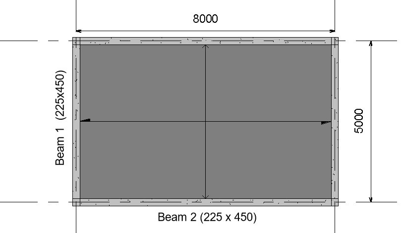
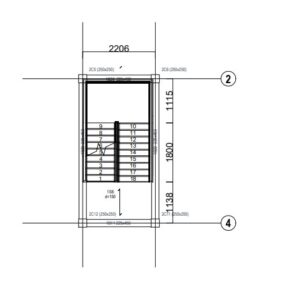
The image below shows the Plan view of a reinforced concrete structure, use the data given below to design Beam 2
Design Data:
Variable load on slab = 5KN/m2
Finishes = 1.5KN/m2
Unit weight of concrete = 24KN/m3
Compressive strength of concrete (fck) = 30N/mm2
Characteristic Strength of main reinforcement (fyk) = 500N/mm2
Characteristic Strength of Shear reinforcement (fyv) = 500N/mm2
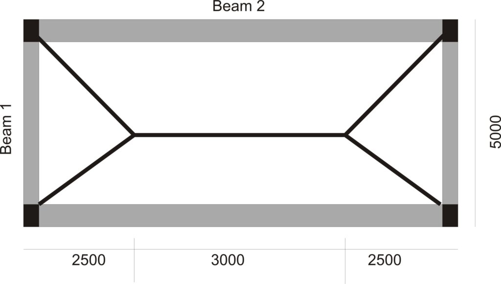
To design Beam 2, we will first distribute the slab loads on the beam and then analyze the beam to compute its internal forces. As shown in fig (2) below the tributary area of slab loads on beam 2 is a trapezium, hence we compute and distribute the slap loads on it as follows:
However, to understand the process of distributing slab load to beams in detail, read, “Distribution of Slab loads to beams.”
Analysis
Permanent Load
Characteristic Self-weight of slab = 0.2 x 24 = 4.8KN/m2
Partition Load on Slab = 1.5KN/m2
Characteristic Permanent Load on Slab = 4.8 + 1.5 = 6.38KN/m2
Area of Slab load Supported by Beam 2 = (0.5 x (8 + 3) x 2.5)/8 = 1.73m2
Permanent Load of Slab on Beam 2 = 1.72 x 6.38 = 10.97KN/m
Self-weight of beam = 0.23 x 0.45 x 24 = 2.48KN/m
Total Permanent Load on beam = 10.97 +2.48 = 13.5 KN/m
Variable Load
Variable load on slab = 5KN/m2
Area of Slab load Supported by Beam 2 = (0.5 x (8 + 3) x 2.5)/8 = 1.73m2
Characteristic Variable Load of Slab on Beam 2 = 1.258 x 5 = 8.59KN/m
Total Design Load
Ultimate Load acting on beam 2 = 1.35(13.5) + 1.5(8.59) = 31.11KN/m
Computation of Internal Forces:
The beam is assumed to be simply supported for ease of analysis.
M = w x L2/8 = 31 x 82/8 = 248KNm
V = W x L/2 = 31 x 8/2 = 124KNm
Design
flexural strength design
- Calculate the effective depth
Assumptions
Cover = 25mm
Main reinforcement diameter = 16mm
Diameter of links = 10mm
Effective depth = h-c-ᴓ-ᴓ/2
=450-25-10-16/2
= 407mm
2. Effective flange width:
beff = beffj + bw
But beffj = 0.2bi + 0.1Lo ≤ (0.2lo, bi)
= 0.2 x (5000 – 225)/2 + 0.1 x 0.85 x 8000
= 0.2 x 2387.5 + 0.1 x 6800
= 1157.5 ≤ (0.2 x 6800, 2387.5)
= 1157.5 ≤ (1360, 2387.5)
beffj = 1157.5
Substitute the value of beffj into the main equation to calculate beff
beff = 1157.5 + 225 ≤ b
= 1382.5 ≤ (1157.5 x2 + 225)
= 1382.5 ≤ (2540)
beff = 1382.5
3. Check whether section is to be designed as singly or doubly reinforced beam
$
K\,=\,\,\frac{M}{bd^2f_{ck}}
$
$
K\,=\,\,\frac{248×10^6}{1382.5×450^2×30}
$
= 0.22
Since K (0.22) < K’ (0.168); design as singly reinforced.
NB: The same beam which was initially designed as doubly reinforced here is now declared to be designed as singly reinforced. This is the effect of the flange width which has augmented the compressive strength of the beam so that no reinforcement is required to resist compressive stress.
4) Calculate the lever arm (Z)
$
Z\,\,=\,\,d\left( 0.5+\sqrt{\text{0.25}-\,\,\frac{K}{1.134}} \right)
$
$
Z\,\,=\,\,407\left( 0.5+\sqrt{\text{0.25}-\,\,\frac{0.22}{1.134}} \right)
$
Since 393.6 < 0.95d (386.7): use Z = 386.7
5) Calculate the area of steel required
$
A_{st\,\,=\,\,\frac{M_{Ed}}{0.87f_{yk}Z}}
$
$
A_{st\,\,=\,\,\frac{248×10^6}{0.87x500x386.7}}
$
Ast = 1474.9mm2
Provide 8T16 (1599mm2)
NB: You will observe that the area of tension reinforcement is large, this can be attributed to the 8m long span of the beam, and more overriding, the assumption that the beam is simply supported which then result in large span moment.
6) Check whether the area of tensile steel provided satisfies minimum area requirement
Asmin = 0.26 (fctm/fyk )bt d
= 0.26 (2.9/500) 225 x 407
= 138.095mm2
Since Ast (1474.9mm2 )> Asmin (138.095mm2), hence minimum area requirement satisfied.
6) For practical purpose of forming a reinforcement cage, provide compression reinforcement as secondary reinforcement which will serve as hanger bars
Asc = 0.2×1474
=294.9mm2
Provide 2T12
Vertical Shear Design
- Check whether the concrete section can resist the shear force without shear reinforcement
VRdc = (0.12K(100ρLfck)1/3 + K1σcp) bwd
K = (1 +√200/d) = 1 + (200/407)0.5 = 1.7
ρL = Asl/bwd = 1474/225 x 407 = 0.016
VRdc = (0.12 x 1.7 (100 x 0.016 x 30) 1/3) 225 x 407
VRdc = 75.3KN
Since VRdc (75.3KN) is less than VEd (124KN) then shear reinforcement has to be designed for.
2. Calculate the shear resistance using ϴ = 22
VRdmax(22) = 0.124bwd(1 – fck/250)fck
= 0.124 x 225 x 407 (1 – 30/250)30
= 299.8KN
Shear resistance of links at ϴ = 22 is adequate
3. Calculate Asw/s at ϴ = 22
$
\frac{A_{sw}}{s}\,\,\,\,=\,\,\frac{V_{Ed}}{0.78xf_{yk}d\cot 22}
$
$
\frac{A_{sw}}{s}\,\,\,\,=\,\,\frac{124×10^3}{0.78x407x500\cot 22}
$
$\frac{A_{sw}}{s}\,\,\,\,$ = 0.3
4. Check whether $\frac{A_{sw}}{s}\,\,\,\,$ satisfy the minimum requirement specified by the code.
$$
\frac{A_{sw\min}}{s}\,\,\,\,=\,\,\frac{0.08x\sqrt{f_{ck}}xb_w}{f_{yk}}
$$
$$
\frac{A_{sw\min}}{s}\,\,\,\,=\,\,\frac{0.08x\sqrt{30}x225}{500} $$
= 0.2
Since Asmin/s (0.2) is less than As/s (0.3), shear reinforcement is greater than the required minimum area of reinforcement.
Calculate shear link reinforcement spacing requirement
Assume two-legged shear reinforcement of 10mm is to be used.
Area of 10mm shear reinforcement = 78.58mm2
Area of two-legged 10mm links = 2x 78.58 = 157mm2
157/s = 0.3
s= 157/0.3
s = 497.9mm
6) Check whether maximum spacing requirement is satisfied
Smax = 0.75xd
= 0.75 x 407
= 305mm
Since the maximum spacing (305mm) is less than the calculated spacing of links (497.9mm), the maximum spacing limit governs the design.
provide Y10 @ 300mm spacing.
Longitudinal Shear Design
- Calculate the shear stress in the flange
$
v_{ED\,\,=\,\,}\frac{\varDelta F_d}{h_f\,\,X\,\,\varDelta x}
$
$
\varDelta F_d\,\,=\,\,\frac{\varDelta M}{d\,\,-\,\,h_f/2}\,\,X\,\,\frac{b_{eff}\,\,-\,\,\frac{b_w}{2}}{b_{eff}}
$
∆X = L/4 = 8000/4 = 20000
∆M = 3WL2/32
= 3 x 31 x 82/32
=186KNM
$\varDelta F_d\,\,=\,\,\frac{186 X 10^8}{407\,\,-\,\,200/2}\,\,X\,\,\frac{1157.5}{1382.5}
$
∆Fd= 507.3KN
$
v_{ED\,\,=\,\,}\frac{507.3 X 10^3}{200\,\,X\,\,2000}
$
2.Check the strength of the compressive structs.
The compressive struct is checked for the minimum strength assuming ϴf = 26.5
Using $
v_{ED}\,\,=\,\,vf_{cd}\sin \theta _f\cos \theta _f
$
v = 0.6(1 – fck/250)
Substitute v into the main equation
$
v_{ED}\,\,=\,\,0.6(1 – 30/250) X 30/1.5 Sin26.5 Cos26.5
$
4.2N/mm2
Since 4.2N/mm2 is greater than 1.27N/mm2, compressive structs is adequate.
3. Check whether transverse reinforcement is required.
if vEd ≤ 0.4 fctd; no transverse shear reinforcement required.
0.4 fctd = 0.27fctk
For C25/30, fctk(0.05) = 2.03
0.4 fctd = 0.27 x 2.03
=0.55
Since vEd > 0.4 fctd; transverse shear reinforcement is required.
4. Design for transverse reinforcement
$
\frac{A_{sf}\,\,X\,\,f_{yd}}{s_f}\,\,=\,\,\frac{V_{Ed}X\,\,h_f\,\,}{\cot \theta _f}
$
$
\frac{A_{sf}\,\,X\,\,0.86 X 500}{s_f}\,\,=\,\,\frac{1.27\,\,200\,\,}{\cot 26.5}
$
Asf/sf = 0.29
Assume the diameter of rebar to be 12mm
Area of rebar = 113
sf = 113/0.29
Sf = 389
Provide Y12@300mm spacing
Deflection Check
- Calculate the actual span-effective depth ratio
Span/depth ratio = 8000/407 = 19.7
2. Calculate the limiting Span-effective depth ratio
l/d = K[11 + 1.5√fck ρ0/ρ + 3.2√fck (ρo/ρ – 1)3/2] if ρ ≤ ρo
l/d = K[11 + 1.5√fck ρo/ρ + 3.2√fck √ρo/ρ ] if ρ > ρo
ρ = Asprovided/b x d
ρ = 1599/225 x 407
= 0.017
ρo = 10-3√fck
ρo = 10-3√30
= 0.005
K = 1 (for simply supported)
Since ρ > ρo = then we will use
l/d = K[11 + 1.5√fck ρo/ρ + 3.2√fck √ρo/ρ ]
l/d = [11 + 1.5√30 0.005/0.019 + 3.2√30 √0.005/0.019]
= 14.3mm
Since actual span-effective depth ratio (19.7) is greater than the limiting span-effective depth ratio (14.3), the beam fails deflection check.
NB: Since the beam fails deflection check, it shall be resized by increasing its depth so as to reduce the span-depth ratio. Another effective solution is to design the beam as encastre beam fixed at both ends; this will reduce its overall deflection as well as its sagging moment which will result to the decrease in the area of tensile steel provided for flexural strength of the member.
Your article helped me a lot, is there any more related content? Thanks!
Can you be more specific about the content of your article? After reading it, I still have some doubts. Hope you can help me.
Wow, incredible blog layout! How long have you been blogging for?
you make blogging look easy. The overall look of your web site is great, as well as the
content!
It’s awesome to visit this website and reading the views of all colleagues about this paragraph,
while I am also eager of getting know-how.
Very good blog! Do you have any tips for aspiring writers?
I’m planning to start my own blog soon but I’m a little lost
on everything. Would you suggest starting with a free platform like WordPress or go for a paid option?
There are so many options out there that I’m completely confused ..
Any recommendations? Thank you!
Howdy! This is my first comment here so I just wanted
to give a quick shout out and tell you I truly enjoy reading your blog posts.
Can you recommend any other blogs/websites/forums that go over the same topics?
Many thanks!
Greetings! I know this is somewhat off topic but I was wondering which blog platform are you using for this
site? I’m getting tired of WordPress because
I’ve had problems with hackers and I’m looking at options for another platform.
I would be awesome if you could point me in the direction of a good
platform.
I’m more than happy to discover this great site.
I wanted to thank you for ones time for this wonderful read!!
I definitely enjoyed every part of it and I have
you book-marked to look at new information in your web
site.
It’s perfect time to make some plans for the future and it is time to
be happy. I’ve read this post and if I could I want to suggest you few interesting things or advice.
Maybe you could write next articles referring to
this article. I wish to read even more things about it!
I always used to study post in news papers but now as I am a user of web thus from now I am using net for articles or reviews,
thanks to web.
Hi i am kavin, its my first occasion to commenting anywhere, when i read this article i thought i could also create comment due to this sensible
post.
Thanks designed for sharing such a good thought,
paragraph is good, thats why i have read it completely
Good answer back in return of this difficulty with solid arguments and explaining everything about that.
I’m amazed, I have to admit. Rarely do I come across a blog that’s both equally educative and
interesting, and let me tell you, you’ve hit the
nail on the head. The issue is something which too few folks
are speaking intelligently about. I am very happy
that I found this during my search for something regarding this.
Good post. I learn something totally new and challenging on websites I stumbleupon every day.
It’s always interesting to read articles from other writers and
use something from other web sites.
I’m really enjoying the design and layout of your site.
It’s a very easy on the eyes which makes it much more enjoyable for me to come here and visit
more often. Did you hire out a designer to create your theme?
Exceptional work!
Pretty great post. I simply stumbled upon your blog and wanted to say that I
have really enjoyed browsing your blog posts. After all I’ll be subscribing
on your feed and I’m hoping you write once more very soon!
I’m really impressed with your writing skills and also with the layout on your weblog.
Is this a paid theme or did you modify it yourself?
Anyway keep up the excellent quality writing, it’s rare to see
a nice blog like this one today.
Spot on with this write-up, I truly believe this web site needs far more attention. I’ll probably be returning to read
more, thanks for the info!
I’ve been surfing on-line more than three hours
as of late, but I by no means discovered any
interesting article like yours. It’s beautiful worth enough for me.
In my view, if all website owners and bloggers made good content as you probably did, the internet shall be
much more useful than ever before.
Keep this going please, great job!
I like the valuable info you provide in your
articles. I will bookmark your weblog and check again here frequently.
I’m quite certain I will learn a lot of new stuff right here!
Good luck for the next!
Hello, i think that i saw you visited my website thus i came to “return the favor”.I’m attempting to find things to enhance my website!I suppose its ok to use a few of your ideas!!
It’s truly a great and useful piece of information. I’m happy that you simply shared this useful information with
us. Please keep us up to date like this. Thanks for sharing.
I constantly emailed this weblog post page to all my associates,
since if like to read it afterward my contacts will too.
Hey there are using WordPress for your blog platform?
I’m new to the blog world but I’m trying to get started and create
my own. Do you require any coding knowledge to make your own blog?
Any help would be really appreciated!
Hi are using WordPress for your site platform? I’m new to the
blog world but I’m trying to get started and create my own. Do you
require any html coding expertise to make your own blog?
Any help would be really appreciated!
You should take part in a contest for one of the most useful blogs on the net.
I will recommend this site!
Great beat ! I would like to apprentice while you amend your site,
how can i subscribe for a blog site? The account aided me a
acceptable deal. I had been tiny bit acquainted of this your broadcast offered bright
clear concept
Attractive element of content. I simply stumbled upon your website and
in accession capital to assert that I get actually enjoyed account your blog posts.
Anyway I will be subscribing for your feeds and even I fulfillment you get admission to consistently fast.
I am sure this paragraph has touched all the internet viewers, its really really nice
article on building up new weblog.
Hello there I am so grateful I found your web site, I really found you by mistake, while I was
researching on Bing for something else, Anyways I am here now and would
just like to say cheers for a remarkable post and a all round entertaining blog (I also
love the theme/design), I don’t have time to read through it all
at the minute but I have saved it and also added in your RSS feeds,
so when I have time I will be back to read a lot more, Please do keep
up the superb work.
Hey! Would you mind if I share your blog with my
myspace group? There’s a lot of people that I think would really enjoy your content.
Please let me know. Thank you
These are in fact impressive ideas in on the topic of blogging.
You have touched some fastidious factors here. Any way keep up wrinting.
bookmarked!!, I really like your site!
Hi to every body, it’s my first pay a quick visit of this website; this web site includes
remarkable and really good stuff designed for visitors.
A person essentially lend a hand to make severely articles I’d state.
That is the first time I frequented your web page and thus far?
I amazed with the analysis you made to create this actual put up extraordinary.
Fantastic activity!
Howdy! Would you mind if I share your blog with my twitter group?
There’s a lot of folks that I think would really appreciate your content.
Please let me know. Many thanks
I know this if off topic but I’m looking into starting my own weblog and was curious what all is needed to
get setup? I’m assuming having a blog like yours would cost a pretty penny?
I’m not very web savvy so I’m not 100% positive.
Any recommendations or advice would be greatly
appreciated. Thank you
Thanks for any other fantastic post. Where else may just
anybody get that kind of info in such an ideal method of
writing? I have a presentation subsequent week, and I am on the
look for such info.
This is my first time go to see at here and i am really happy to read all at single place.
Does your website have a contact page? I’m having trouble locating
it but, I’d like to send you an email. I’ve
got some creative ideas for your blog you might be interested in hearing.
Either way, great website and I look forward to seeing it grow over time.
We are a group of volunteers and starting a new scheme in our community.
Your web site offered us with valuable information to
work on. You’ve done an impressive job and our
entire community will be grateful to you.
Nice post. I was checking continuously this blog and I am impressed!
Very useful information specially the closing phase 🙂 I maintain such info much.
I used to be seeking this particular info for a long time.
Thank you and good luck.
Thank you, I have just been looking for information about this subject for a
long time and yours is the greatest I’ve found out till now.
But, what about the bottom line? Are you positive concerning
the source?
constantly i used to read smaller content that
also clear their motive, and that is also happening with this post which I am reading at this time.
Heya i抦 for the first time here. I found this board and I to find It truly helpful & it helped me out much. I am hoping to provide something again and help others such as you helped me.
I have been browsing on-line greater than 3 hours nowadays, but I never discovered any fascinating article like yours. It’s beautiful worth enough for me. Personally, if all webmasters and bloggers made excellent content material as you probably did, the internet might be much more helpful than ever before. “It’s all right to have butterflies in your stomach. Just get them to fly in formation.” by Dr. Rob Gilbert.
секс ангарск зоо порно лижет
пизду секс с трансом луганск видео для взрослых глубокий минет
gNDHyQJLXheY