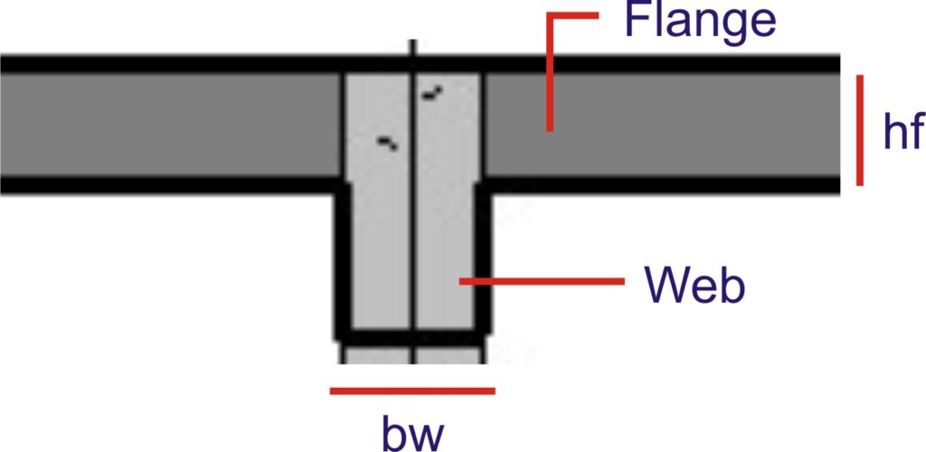
A flange section is that which has a rectangular extension from the main rectangular body. The extension is called a flange while the rectangular body is called web. This type of section mostly occurs when a beam is cast monolithically with a slab.
The design of a flange beam is similar to that of a rectangular beam only that the flange gives additional area of concrete which adds to the overall compressive strength of the section. So instead of using the breadth of the rectangular section only in estimating the compressive strength of the section, the breath of the rectangular section plus that of the flange is used thereby augmenting the compressive strength of the beam. This increase in compressive strength means flange beams, when the flanges are in compression throughout the member as in the case of a simply supported beam, rarely require to be designed as doubly reinforced.
However, it is very pertinent to note that this increase in compressive strength due to the flange area will be valid only when the flange is in compression. Whenever the flange is in tension as in the case above columns in a continuous beam, the section should be designed as a rectangular beam as more concrete area in tension will actually serve little or no purpose.
Types of Flange Section
Flange sections are however categorized based on their geometry. The two basic types are:
- L section
- T section
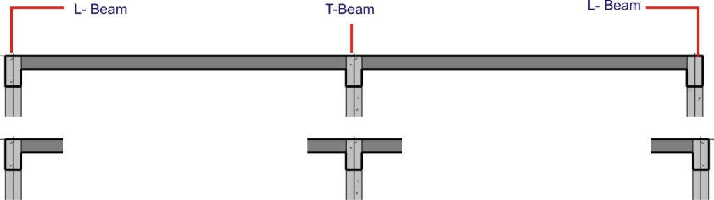
The L sections are mostly found in perimeter beams of building as the slab is only spanning from the beam on one side while the T section on the other hand is mostly found in buildings intermediate beams as slab spans from both sides of the beam.
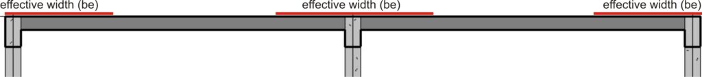
EFFECTIVE WIDTH OF FLANGE
When the flange of a beam is exploited in designing a beam, the total span of the adjoining slab when large does not often act with the supporting beam to resist the loads on the beam, only some portion of the slab does. To calculate the portion of the slab that act together with the beam to resist loads results to the concept of effective width of flange.
The effective flange width according to Eurocode 2 depends on the web and flange dimensions, the type of loading, the span, the support conditions and the transverse reinforcement.
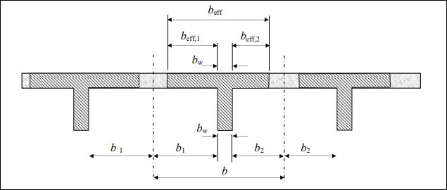
The effective width (beff) of flange according to Eurocode 2 can be calculated as:
$
b_{eff}\,\,=\,\,b_{effj\,\,}+\,\,b_{w\,\,}\leqslant \,\,b
$
Where:
$
b_{effj\,\,}=0.2b_i+0.1l_o\leqslant 0.2l_o
$
beffj <= bi
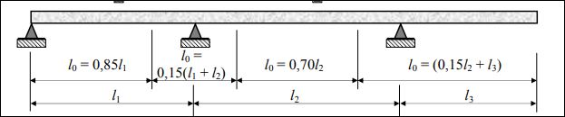
lo is defined as the distance between point where moment is zero. The value of for different support configurations is defined in fig (5) as shown below. Other parameters in the formular are defined in fig (4)
Click to also Read: Design of Reinforced Concrete Flange beam to Eurocode 2 – Worked Example
Design of Flange Beam
Flexural design of a Flange beam
For the design of a flange in flexure either of these two cases are expected:
- When the portion of concrete to resist compression lies within the flange
- When the portion of concrete to resist compression lies below the flange.
In designing a flange section, when the area of concrete within the flange section is enough to develop the strength required to resist the compressive force, then the beam is designed as a rectangular section with breath beff (effective flange width). Therefore, the moment of resistance of the section can be calculated using:
Mu = Kbeffd2fck (k = 0.167)
When Mu < M, then the stress block is truly within the flange and the beam is designed as singly reinforced.
The area of tensile reinforcement in this case can be determined using:
$
A_{st\,\,=\,\,\frac{M_{Ed}}{0.87f_{ck}Z}}
$
Where Z which is the lever arm is:
$
Z\,\,=\,\,d\left( \text{0.5}+\sqrt{\text{0.25}-\,\,\frac{K}{1.134}} \right) \,\,\,\,\leqslant \,\,0.95d
$
Although Eurocode 2 (EC2) does not limit the lever arm to 0.95d, it is a good practice nonetheless to limit it as such in accordance to British standard.
When the stress block to resist compressive force extends below the flange, then these can be designed by either:
- Calculating the exact depth of the web below the flange that is harnessed to resist the compressive force.
- By conservatively assuming that the neutral axis depth is equals to maximum value allowed by the code which 0.45d.
To calculate the actual depth of the web that partakes in resisting compression can be very tedious, as a work around, the author prefers conservatively taking the depth of the web that resist compression to be 0.45d.
Consequently, the moment of resistance of the section will be the moment of resistance of the flange plus the moment of resistance of the web.
ie: Mu = Mf + Mw
0.156fck(befff – bw)(d – hf/2)hf + 0.167fckbd2
If the design moment (M) is greater than the moment obtained after evaluating the above formula, then the section shall be designed as doubly reinforced.
After analyzing a T-beam section In Reinforced Concrete Design to Eurocode 2 by Mosley, Bungey, and Hulse; the formula for calculating the area of tensile reinforcement for singly reinforced section when the depth of the neutral axis is assumed as 0.45d is rendered as:
$
A_s\,\,=\,\,\frac{M\,\,+\,\,0.1f_{ck}b_wd\left( 0.36d\,\,-\,\,h_f \right)}{0.87f_yk\left( d\,\,-\,\,0.5h_f \right)}
$
Vertical Shear Design
Shear force is an internal force that tends to make the part of a structural member slide against another. It is often significant close to supports and under point loads. BS EN 1992-1-1: 2004 adopts the approach of variable strut inclination method for shear design; this method allows for flexibility in the angle of inclination of the compressive strut between 22 and 45.
Shear resistance of section without Shear reinforcement
Before shear reinforcement are designed, it is important that the concrete section is checked whether it has sufficient shear capacity (VRd.c) to resist the maximum design shear force (VEd) that will act on it without shear reinforcement. The shear capacity of the concrete section without shear reinforcement is often sufficient for lightly loaded beams of minor importance, however minimum area of shear reinforcement is always provided.
For member which shear reinforcement is not required, the shear capacity is given in section 6.2.2 (1) as:
VRdc = (CRdcK(100ρLfck)1/3 + K1σcp) bwd
σcp = NEd/Ac, hence where there is no axial force the equation is reduced to:
VRdc = {CRdcK(100ρLfck 1/3}bwd
From EC2 and Table NA.1 from of the UK National Annex to the code CRdc = 0.18/ϒ, hence the formular becomes:
VRdc = {0.12K(100ρLfck)1/3}bwd
This section resistance must not, however, be less than the permitted minimum resistance which is:
VRdc = {0.035K3/2fck1/2}bwd
where:
K = (1 +√200/d) ≤ 2.0
ρL = Asl/bwd ≤ 0.02
The Variable Strut Inclination Method
As for section which has the member shear capacity (VRdc) less than the design shear force (VRdc) the shear reinforcement is required and designed using the variable strut inclination method. This method is based on an imaginary truss model where concrete acts as the top chord and also acts as the diagonal strut members inclined at an angle ϴ, the bottom chords are the main tensile reinforcement while the designed links serve as the transverse tension members. The angle ϴ changes in value proportionately to the shear force acting on the member. The angle ranges between the lower and upper limit of 22 and 45 degrees respectively. It should be noted that in this imaginary truss, the contribution of the concrete to shear resistance is ignored.
Before the vertical stirrup is designed, it is important to check whether the design shear force is not too large enough to cause the crushing of the inclined compressive strut. To ensure this does not happen, the maximum resistance of the section must be greater than the design shear force.
ie: VRdmax > VEd
The formula for VRdmax is given in equation (6.9) of the code as:
VRdmax = ∝cwbwZv1cd/(cotϴ + tanϴ)
When the value of V1 in accordance with equation (6.6N) of the code and ∝cw = 1.0 are entered into the formula, it can be further simplified as:
VRdmax = (0.36bwd(1-fck/250)fck)/(cotϴ + tanϴ)
The value of ϴ to be used to check whether the section is adequate such that the compressive strut is not crushed is 45 degrees as this is the highest value of ϴ allowed by EC2 which gives the maximum resistance. When 45 is substituted for ϴ then the equation becomes:
VRdmax(45) = 0.81bwd(1 – fck/250)fck
Should VRdmax be less than VEd, the compressive strut will fail by crushing so the section is inadequate and have to be resized. However, if VRdmax is greater than VEd then we can proceed to designing the vertical links that will be required to resist the shear in the member. Different values of ϴ can be tried to achieve a shear resistance greater than the design shear force. The first value to be tried is 22 degrees as this angle gives the least resistance. If substituting 22 for ϴ does not give sufficient resistances, then a higher value of ϴ will be tried.
As an alternative and easier workaround to trying different values for ϴ until a suitable one is found, the design shear force should be equated to VRdmax so that ϴ is made the subject of the formular and a suitable value of ϴ is obtained in one swoop. Thus:
VEd = (0.36bwd(1 – fck/250)fck)/(cotϴ + tanϴ)
Once the perfect value of ϴ is obtained having modified the above equation to make ϴ the subject of the formular, this value can be plugged into the equation below: To get the shear resistance of a vertical stirrup of area Asw and spacing s, the code gives the equation to be used as:
VRd,s = (Asw/s)ZfywdCotϴ
Where; fywd = design yield strength of shear reinforcement.
The ratio of the Area and spacing of the link should not however be less than the minimum ratio as given in equation (9.5N) thus:
Asw/s = 0.08bw(√fck/fywk)
Additional Longitudinal tension reinforcement
There’s always need to provide additional longitudinal tension reinforcement at the bottom face of the section to resist the horizontal component of the force in the inclined strut. The required force to be resisted is given in equation (6.18) of EC2 which goes:
Ftd: 0.5VEd(Cotϴ – Cotα)
For all practical purpose, when curtailment length of longitudinal bars is increased beyond the position where they are not needed, then required force to counteract the longitudinal component of the force on the strut is unwittingly provided, hence separate calculation for additional longitudinal steel is often superfluous.
Longitudinal Shear Design
Longitudinal shear stress (vED) occurs along the interface between the flange and the web of a flange beam. This longitudinal shear stress is a result of the change in the longitudinal force acting at different positions along the beam. The variation of this longitudinal force is as a result of the deformation of the beam under bending.
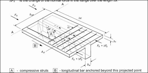
Transverse reinforcement over full effective flange width should be provided at the top face of the flange to resist this longitudinal shear stress. These reinforcement act as tension ties while the concrete flange act as compressive structs in an assumption similar to that in vertical shear design of a rectangular beam.
The shear stress in the flange can be evaluated using:
$
v_{ED\,\,=\,\,}\frac{\varDelta F_d}{h_f\,\,X\,\,\varDelta x}
$
where:
∆x is the length under consideration (The maximum value of ∆x is half of the distance between point where moment is 0 and where moment is maximum for simply supported beam)
$
\varDelta F_d\,\,=\,\,\frac{\varDelta M}{d\,\,-\,\,h_f/2}\,\,X\,\,\frac{b_{eff}\,\,-\,\,\frac{b_w}{2}}{b_{eff}}
$
∆M is the change in moment over the distance ∆x.
As with vertical shear, it is also necessary to check whether the compressive struct in the flange will not crush under the shear stress. To verify this, the equation below must be satisfied:
$
v_{ED}\,\,=\,\,vf_{cd}\sin \theta _f\cos \theta _f
$
EC2 gives a range of angle of inclination of the struct whether the flange is in tension or compression as shown below:
26.50 ≤ ϴf ≤ 450 OR 1.0 ≤ cotϴf ≤ 2.0 (for flanges in compression)
38.60 ≤ ϴf ≤ 450 OR 1.0 ≤ cotϴf ≤ 1.25 (for flanges in tension)
The transverse reinforcement required by the flange beam can be evaluated using:
$
\frac{A_{sf}\,\,X\,\,f_{yd}}{s_f}\,\,=\,\,\frac{V_{Ed}X\,\,h_f\,\,}{\cot \theta _f}
$
If the longitudinal shear acts together with transverse bending of the flange as in a cantilever, the transverse reinforcement will be the greater of:
a) $
\frac{A_{sf}\,\,X\,\,f_{yd}}{s_f}\,\,=\,\,\frac{V_{Ed}X\,\,h_f\,\,}{\cot \theta _f}
$
b) $
\frac{A_{sf}\,\,X\,\,f_{yd}}{s_f}\,\,=\,\,\frac{V_{Ed}X\,\,h_f\,\,}{\cot \theta _f}
$ + Asf X b/2sf X b
On no account should the area of transverse reinforcement be less than Asmin given by:
$
\frac{A_{s\min}}{b\,\,X\,\,d_f}\,\,>\,\,\text{0.26}X\frac{f_{ctm}\,\,}{f_{yk}}\,\,>\,\,\text{0.0013}
$
It is however worthy of note that should vEd is less than or equal to 40percent of the cracking tensile strength of the concrete (fctd then no transverse reinforcement is required.)
Ie: vEd ≤ 0.4 fctd; no transverse shear reinforcement required.
Where: 0.4 fctd = 0.4 X fctk/1.5 = 0.27fctk
Deflection Check
Deflection is an important serviceability limit state that must be checked whether its limit is not exceeded. Excessive deflection can compromise the aesthetic of the structure, give impression of unsafe structure, cause damage to brittle finishes, cause problem to fixtures etc. So ensuring deflection limit is not exceeded is one of the important criteria of beam design.
The factors affecting deflection of beams are numerous likewise is calculating deflection for heterogenic material like reinforced concrete very tedious. Quasi-permanent load combination is considered for deflection; this entails considering the permanent load plus some percentage of the variable load. A fraction of the variable load is considered because the element is not expected to be exposed to the full extent of variable load consistently for long term.
The code suggests that the deflection of a beam can be estimated by calculating the curvature of the beam when un-cracked and when cracked. But a less tedious approach is to limit the span-depth ratio as this in turn limit the possible curvature of the beam. The limiting span-depth ratio can be estimated using equations below:
l/d = K[11 + 1.5√fck ρ0/ρ + 3.2√fck (ρo/ρ – 1)3/2] if ρ ≤ ρo
l/d = K[11 + 1.5√fck ρo/ρ + 3.2√fck √ρo/ρ ] if ρ > ρo
The definition of the symbols in the formulas can be found under clause 7.4.2 (2) of the code.
When the ratio of the flange breath the web breadth is greater than 3, the limiting value for deflection should be multiplied by 0.8. It should also be put into consideration that the code assumes the steel stress at serviceability limit state at critical section of an element is 310MPa. This stress corresponds with yield stress of 500MPa. If other serviceability stress is used, then the equation for the limiting span-depth ratio should be modified accordingly by multiplying it by 310MPa/rows.
When the span-depth ratio of the member falls under the limiting value, it is inferred that the member has passed deflection criteria and has conformed to the code’s objective, which is to limit the deflection of the member to Span/250 or span/500 for members with brittle finishes or vulnerable adjacent part. Should the actual span-depth ratio of the member exceed the limiting span-depth ratio, the member is said to have failed deflection criteria and should therefore be redesigned.
References:
BS EN 1992-1-1: 2004 (Eurocode 2: Design of Concrete Structures)
Renforced Concrete Design to Eurocode 2 by W.H. Mosley, J.H.Bungey, and Ray Hulse
Your article helped me a lot, is there any more related content? Thanks!
Excellent web site you have here.. It’s difficult to find quality
writing like yours these days. I really appreciate people like you!
Take care!!
I love what you guys are usually up too. This sort of clever work
and coverage! Keep up the amazing works guys I’ve you guys to my personal blogroll.
I know this if off topic but I’m looking into starting my own blog and was curious what all is needed to get setup?
I’m assuming having a blog like yours would cost a pretty penny?
I’m not very web smart so I’m not 100% certain.
Any suggestions or advice would be greatly appreciated.
Thanks
My programmer is trying to convince me to move
to .net from PHP. I have always disliked the idea because of the expenses.
But he’s tryiong none the less. I’ve been using Movable-type on numerous websites for about a
year and am anxious about switching to another
platform. I have heard fantastic things about blogengine.net.
Is there a way I can import all my wordpress posts
into it? Any help would be really appreciated!
great issues altogether, you just won a brand new reader.
What would you suggest about your post that you just
made a few days in the past? Any certain?
Pretty! This was an incredibly wonderful article.
Many thanks for supplying this info.
Hello! I’ve been reading your site for a while now and finally got the bravery to go ahead and give you a shout out from Houston Texas!
Just wanted to mention keep up the fantastic job!
Do you mind if I quote a couple of your posts as long as I provide credit
and sources back to your blog? My website
is in the very same area of interest as yours and my users would definitely benefit
from a lot of the information you present here. Please let me know if this alright with you.
Cheers!
Hi, I do believe this is an excellent web site. I stumbledupon it 😉 I will return once again since i have book-marked it.
Money and freedom is the greatest way to change, may you be rich
and continue to guide others.
Hi, Neat post. There’s an issue along with your site in internet explorer,
could test this? IE nonetheless is the marketplace chief and a large component to
other people will leave out your wonderful writing due to this problem.
I got this website from my buddy who told me concerning this web page and at the moment
this time I am browsing this site and reading very informative content at this time.
What’s Taking place i am new to this, I stumbled upon this I’ve found It absolutely useful and it has helped me out
loads. I am hoping to give a contribution & help different users like
its aided me. Great job.
Excellent post. I will be going through many of these
issues as well..
I got this site from my pal who informed me on the topic of this site and now this time I am visiting this
web page and reading very informative articles at this place.
Please let me know if you’re looking for a author for your site.
You have some really great articles and I feel I would be a good asset.
If you ever want to take some of the load off, I’d
love to write some material for your blog in exchange for a link back
to mine. Please blast me an email if interested.
Regards!
Excellent way of telling, and good article to obtain facts regarding my
presentation subject, which i am going to convey in institution of higher education.
Pretty part of content. I simply stumbled upon your website and in accession capital to claim that I acquire in fact loved account your blog posts.
Anyway I will be subscribing for your augment or even I achievement you get right of entry to persistently quickly.
Thank you for the good writeup. It in fact was a amusement account it.
Look advanced to far added agreeable from you! By the way, how can we communicate?
This is really interesting, You are a very skilled blogger.
I have joined your rss feed and look forward to seeking more of your fantastic post.
Also, I’ve shared your site in my social networks!
With havin so much content do you ever run into any issues of plagorism or copyright infringement?
My blog has a lot of exclusive content I’ve either
authored myself or outsourced but it appears a lot of it is popping it up all over the internet without my authorization. Do you know
any methods to help reduce content from being stolen? I’d
definitely appreciate it.
I’m really inspired together with your writing talents as smartly as with the format in your
blog. Is this a paid theme or did you customize it your self?
Either way stay up the excellent high quality writing,
it’s uncommon to see a great weblog like this one nowadays..
We stumbled over here different page and thought I may as well check things out.
I like what I see so i am just following you. Look forward to checking out your web page for a second time.
Woah! I’m really digging the template/theme of this website.
It’s simple, yet effective. A lot of times it’s
difficult to get that “perfect balance” between superb usability and appearance.
I must say you have done a great job with this. Additionally, the blog loads extremely quick for me on Chrome.
Exceptional Blog!
It’s really a cool and useful piece of info. I’m satisfied that you just shared this useful info with us.
Please keep us up to date like this. Thank you for sharing.
I’ve been browsing on-line more than 3 hours these days, but I by no means found any attention-grabbing article like yours.
It’s beautiful value sufficient for me. In my view, if all webmasters
and bloggers made just right content as you did,
the net will be a lot more helpful than ever before.
Currently it appears like Expression Engine is the preferred blogging platform available right now.
(from what I’ve read) Is that what you’re using on your
blog?
It’s enormous that you are getting ideas from this post as well as from our argument made at this time.
I’ll immediately grasp your rss as I can not find your e-mail subscription link
or newsletter service. Do you’ve any? Kindly let me understand so
that I may just subscribe. Thanks.
My brother suggested I would possibly like this website. He used to be
entirely right. This submit truly made my day. You can not
believe simply how much time I had spent for this info! Thanks!
After going over a few of the articles on your site, I honestly appreciate your way of
writing a blog. I saved it to my bookmark website list and
will be checking back soon. Please visit my website as
well and tell me what you think.
Good response in return of this matter with
genuine arguments and describing everything on the topic of that.
Thank you a lot for sharing this with all of us
you actually understand what you are talking approximately!
Bookmarked. Please also consult with my website =).
We could have a hyperlink trade arrangement between us
I every time used to read paragraph in news papers but now as
I am a user of net so from now I am using
net for posts, thanks to web.
I loved as much as you’ll receive carried
out right here. The sketch is tasteful, your
authored material stylish. nonetheless, you command get got an impatience over that you wish be delivering the following.
unwell unquestionably come further formerly again since exactly the same nearly very often inside case you shield
this increase.
Excellent beat ! I wish to apprentice while you amend your website, how
can i subscribe for a blog website? The account aided me a acceptable
deal. I had been tiny bit acquainted of this your broadcast
offered bright clear concept
I don’t think the title of your article matches the content lol. Just kidding, mainly because I had some doubts after reading the article.
Undeniably imagine that which you said. Your favorite justification seemed to be at
the web the easiest thing to be mindful of. I say to you, I certainly get irked whilst folks consider worries
that they plainly do not recognise about.
You controlled to hit the nail upon the top and also
defined out the whole thing without having side-effects ,
folks could take a signal. Will probably be again to get more.
Thanks
Helpful information. Fortunate me I discovered your site
by chance, and I’m stunned why this coincidence did not came
about in advance! I bookmarked it.
This is really interesting, You’re a very skilled blogger.
I’ve joined your feed and look forward to seeking more of your excellent post.
Also, I have shared your web site in my social networks!
If some one desires to be updated with hottest technologies afterward he must be pay a visit this web site and be up to date every day.
I have been exploring for a bit for any high quality
articles or blog posts in this kind of space .
Exploring in Yahoo I eventually stumbled upon this
web site. Reading this info So i am satisfied to express that I have a
very good uncanny feeling I discovered just what I needed.
I most without a doubt will make certain to don?t overlook this
site and provides it a glance regularly.
Hello Dear, are you genuinely visiting this web page daily,
if so after that you will without doubt obtain good
know-how.
Thank you for every other excellent post. The place else may just anybody get that type of
information in such a perfect approach of writing? I’ve a presentation next week,
and I’m at the look for such info.
Ahaa, its good dialogue concerning this post here at this webpage, I have read all
that, so at this time me also commenting here.
Thanks for sharing your thoughts about website. Regards
Quality articles is the crucial to interest the viewers to pay a visit
the web page, that’s what this website is providing.
I wanted to thank you for this very good read!! I certainly loved
every bit of it. I’ve got you bookmarked to look at new things you post…
Your way of explaining all in this post is truly pleasant,
every one can easily understand it, Thanks a lot.
Today, while I was at work, my sister stole my iphone and
tested to see if it can survive a 40 foot drop, just so she can be a youtube sensation. My apple ipad is now broken and she has 83 views.
I know this is entirely off topic but I had to share it with
someone!
As the admin of this website is working, no doubt very rapidly it will
be famous, due to its feature contents.
For the reason that the admin of this web page is working, no doubt very soon it will be renowned,
due to its quality contents.
You are so cool! I don’t believe I’ve read through anything like this before.
So good to discover somebody with genuine thoughts on this subject.
Seriously.. many thanks for starting this up. This web site is something that is required on the web, someone with a little originality!
Yes! Finally someone writes about website.
Write more, thats all I have to say. Literally, it seems as though you relied on the video to make your point.
You definitely know what youre talking about, why throw away your intelligence on just posting videos to your
weblog when you could be giving us something enlightening to read?
My family members always say that I am wasting my time here at web, but I know
I am getting know-how everyday by reading such nice
articles or reviews.
This post is invaluable. How can I find
out more?
I pay a visit every day a few sites and information sites to read content, however this weblog
gives feature based content.
When I initially left a comment I seem to have clicked the -Notify me when new comments are added- checkbox and from now on whenever
a comment is added I receive 4 emails with the exact same comment.
Perhaps there is a means you are able to remove me from that service?
Thanks a lot!
I am sure this piece of writing has touched all the internet visitors, its really really good article on building up new blog.
Thank you for the good writeup. It in fact was a amusement account it.
Look advanced to far added agreeable from you! However,
how can we communicate?
Good day! I know this is kinda off topic but I was wondering which blog platform are you using for this site?
I’m getting fed up of WordPress because I’ve had problems with hackers and
I’m looking at options for another platform. I would be awesome if you could point
me in the direction of a good platform.
always i used to read smaller articles which
also clear their motive, and that is also happening with this post
which I am reading at this place.
Attractive section of content. I just stumbled upon your weblog
and in accession capital to assert that I acquire in fact enjoyed account
your blog posts. Any way I will be subscribing to your augment and even I achievement you access
consistently quickly.
Nice post. I learn something totally new and challenging on websites
I stumbleupon on a daily basis. It’s always exciting to read
through articles from other writers and use a little
something from their sites.
Your way of explaining all in this piece of writing is actually good, every one can easily understand it, Thanks a lot.
great put up, very informative. I’m wondering why the opposite specialists of this sector do not realize
this. You should continue your writing. I’m confident, you have a
great readers’ base already!
I’m not that much of a online reader to be honest but your blogs really
nice, keep it up! I’ll go ahead and bookmark your website to come back in the future.
Cheers
First off I would like to say great blog! I had a quick question which I’d
like to ask if you don’t mind. I was curious to find out how you center
yourself and clear your mind before writing. I have had a difficult time clearing my mind in getting my ideas out there.
I do take pleasure in writing but it just seems like the first 10 to 15 minutes
are usually wasted just trying to figure out how
to begin. Any suggestions or hints? Appreciate it!
Fabulous, what a blog it is! This web site provides useful information to us,
keep it up.
You can certainly see your skills within the article you
write. The sector hopes for even more passionate writers like you who aren’t afraid to say
how they believe. All the time follow your heart.
I’m truly enjoying the design and layout of your site. It’s a very easy on the eyes which makes
it much more enjoyable for me to come here and visit more often. Did you hire out
a developer to create your theme? Excellent work!
Hey! I’m at work surfing around your blog from my new iphone!
Just wanted to say I love reading through your blog and look forward to all your posts!
Keep up the outstanding work!
Hello There. I discovered your blog the use
of msn. This is a very neatly written article.
I will be sure to bookmark it and come back to learn extra of your helpful info.
Thanks for the post. I’ll certainly return.
Hello! Someone in my Myspace group shared this website
with us so I came to look it over. I’m definitely loving the
information. I’m bookmarking and will be tweeting this to
my followers! Terrific blog and brilliant style and design.
What i don’t understood is actually how you’re not actually much more smartly-appreciated than you may
be now. You’re so intelligent. You know therefore
considerably relating to this subject, made me for my part consider it from so many numerous angles.
Its like women and men are not interested until it is one thing to do with Lady gaga!
Your personal stuffs great. Always deal with it up!
Thanks for any other informative blog. The place else may just
I get that kind of information written in such an ideal approach?
I’ve a venture that I’m simply now operating on, and I’ve been on the glance out for such information.
Hi, I do think this is an excellent web site. I stumbledupon it 😉 I will
return once again since i have book-marked it.
Money and freedom is the best way to change, may you be rich and
continue to help other people.
Excellent beat ! I would like to apprentice whilst you
amend your site, how can i subscribe for a weblog site?
The account aided me a appropriate deal. I had been a
little bit familiar of this your broadcast provided
bright transparent idea
Pretty nice post. I just stumbled upon your blog and wanted
to say that I have really enjoyed surfing around your blog posts.
In any case I will be subscribing to your rss feed and I hope you write again very soon!
I’m amazed, I must say. Rarely do I encounter
a blog that’s both educative and entertaining, and without a doubt, you have hit the
nail on the head. The issue is something which not enough people
are speaking intelligently about. I am very happy I found this during my hunt
for something relating to this.
If you would like to get much from this article then you
have to apply such strategies to your won webpage.
It’s really very difficult in this active life to listen news on Television, so I just use world wide web for
that purpose, and obtain the newest news.
I was recommended this web site by my cousin. I am not
sure whether this post is written by him as no one else know such detailed about
my difficulty. You’re incredible! Thanks!
I really like what you guys tend to be up too. This type of clever work and exposure!
Keep up the good works guys I’ve incorporated you guys to our blogroll.
This article presents clear idea for the new users of blogging, that really
how to do running a blog.
I was recommended this blog through my cousin. I am now not certain whether or not this submit is written by means
of him as no one else realize such designated about my trouble.
You’re amazing! Thanks!
It’s very easy to find out any matter on web as compared to textbooks, as I found this paragraph at this site.
I don’t even know how I ended up here, but I thought this post was
great. I don’t know who you are but certainly you are going to a
famous blogger if you aren’t already 😉 Cheers!
It’s remarkable to visit this web page and reading the views of all
friends concerning this paragraph, while I am also zealous of getting experience.
We are a group of volunteers and starting a new scheme in our community.
Your site provided us with valuable info to work on. You’ve done an impressive job and our whole community
will be thankful to you.
Very shortly this web site will be famous amid all blogging and site-building
users, due to it’s good articles or reviews
Great website. Plenty of useful info here. I am sending
it to some friends ans additionally sharing in delicious.
And of course, thank you to your effort!
I am curious to find out what blog system
you happen to be utilizing? I’m experiencing some minor security
issues with my latest website and I would like to find something more safe.
Do you have any suggestions?
Because the admin of this web page is working, no hesitation very shortly it will be
renowned, due to its quality contents.
Thanks for sharing such a pleasant idea, paragraph is pleasant, thats why i have
read it completely
Hello just wanted to give you a quick heads up.
The text in your content seem to be running off the screen in Safari.
I’m not sure if this is a format issue or something
to do with internet browser compatibility but I figured I’d post to let you
know. The design and style look great though!
Hope you get the problem resolved soon. Many thanks
I simply could not go away your site before suggesting
that I actually enjoyed the usual information a person supply
in your visitors? Is gonna be again steadily in order to investigate cross-check new posts
I simply could not depart your web site prior to suggesting
that I extremely enjoyed the usual information a person provide for your visitors?
Is gonna be back often in order to check out new posts
What’s up it’s me, I am also visiting this web site
regularly, this site is really good and the users are really sharing good thoughts.
This is a good tip particularly to those fresh to the blogosphere.
Brief but very accurate information… Thanks for sharing this one.
A must read post!
Hello, I think your website might be having browser compatibility issues.
When I look at your blog site in Ie, it looks fine but when opening in Internet Explorer,
it has some overlapping. I just wanted to give you
a quick heads up! Other then that, fantastic blog!
Helpful info. Lucky me I found your website accidentally, and I’m stunned why this coincidence didn’t happened in advance!
I bookmarked it.
Hi colleagues, fastidious paragraph and nice
arguments commented at this place, I am truly enjoying by these.
I’m amazed, I must say. Seldom do I encounter a blog that’s equally educative and entertaining, and without a doubt, you have hit
the nail on the head. The problem is something that too few
men and women are speaking intelligently about. I’m very happy that I found this during
my search for something relating to this.
Definitely imagine that which you said. Your favourite justification appeared to be at the internet the easiest factor to have in mind of.
I say to you, I certainly get irked whilst folks
think about worries that they plainly do not recognize
about. You managed to hit the nail upon the highest and defined out the entire thing without having side-effects , other folks can take a signal.
Will likely be again to get more. Thanks
This paragraph gives clear idea designed for the new users of blogging, that actually how
to do blogging.
Whats up this is kinda of off topic but I was wondering if blogs use WYSIWYG
editors or if you have to manually code with HTML. I’m starting a
blog soon but have no coding experience so I wanted to get advice from someone with experience.
Any help would be greatly appreciated!
Your point of view caught my eye and was very interesting. Thanks. I have a question for you.
Hi there, after reading this amazing article i am as well happy to share my knowledge here with mates.
I’m not sure where you’re getting your info, but great topic.
I needs to spend some time learning much more
or understanding more. Thanks for great information I was looking for this info for my mission.
WOW just what I was looking for. Came here by searching for website
This web site definitely has all the information I needed about this subject and didn’t know
who to ask.
Hello There. I found your blog using msn. This is an extremely well written article.
I will be sure to bookmark it and return to
read more of your useful information. Thanks for the
post. I’ll definitely comeback.
I would like to thank you for the efforts you’ve put in writing this blog.
I’m hoping to see the same high-grade blog posts by you in the future as well.
In fact, your creative writing abilities has inspired me to get my very own website now
😉
Howdy are using WordPress for your blog platform?
I’m new to the blog world but I’m trying to get started and create my own. Do you need any html coding expertise
to make your own blog? Any help would be really
appreciated!
Asking questions are in fact pleasant thing if you are not understanding anything entirely, however this piece
of writing presents nice understanding yet.
Everything is very open with a precise description of the challenges.
It was really informative. Your website is useful.
Many thanks for sharing!
Hello, Neat post. There’s a problem with your website in internet explorer,
might test this? IE still is the market leader and a large portion of other people will miss your wonderful writing because of
this problem.
magnificent points altogether, you just received a emblem new reader.
What would you suggest about your submit that you simply
made a few days in the past? Any certain?
It’s actually a nice and useful piece of information. I am satisfied that you just shared this useful information with us.
Please stay us up to date like this. Thanks for sharing.
I am not positive the place you’re getting your info,
however great topic. I needs to spend a while finding out much more or
figuring out more. Thank you for fantastic information I was looking for this
info for my mission.
Just desire to say your article is as surprising. The clearness for your put up is simply cool and that i could suppose you are a professional
in this subject. Well along with your permission let me to clutch your feed to keep up to date with drawing close post.
Thanks one million and please carry on the rewarding work.
It’s a pity you don’t have a donate button! I’d certainly donate to this outstanding blog!
I guess for now i’ll settle for book-marking and adding your RSS feed
to my Google account. I look forward to fresh updates and will share this website with my Facebook group.
Talk soon!
If some one wants to be updated with most recent technologies then he
must be pay a visit this web page and be up to date all the time.
Pretty! This has been an extremely wonderful article. Thank you
for supplying this info.
I was very pleased to find this web site. I need to to thank you for
ones time due to this fantastic read!! I definitely liked every little bit of it and I have
you saved as a favorite to look at new information in your site.
What’s up, after reading this remarkable
paragraph i am also cheerful to share my experience here with friends.
Great blog! Is your theme custom made or did you download it from
somewhere? A theme like yours with a few simple adjustements would really
make my blog jump out. Please let me know where you got your design. With thanks
Keep on writing, great job!
Thanks for another great article. The place else may just anyone get that kind of information in such an ideal way of writing?
I’ve a presentation subsequent week, and I’m at the look for such information.
It’s an amazing piece of writing designed for all the internet people; they
will get advantage from it I am sure.
Very shortly this site will be famous among all blogging and site-building people, due
to it’s fastidious articles or reviews
I’m impressed, I have to admit. Rarely do I come across a blog that’s both equally educative and entertaining, and without a doubt, you have hit the nail
on the head. The issue is an issue that too few men and women are speaking intelligently about.
I am very happy I stumbled across this during my search for something concerning this.
Does your website have a contact page? I’m having trouble
locating it but, I’d like to shoot you an email.
I’ve got some recommendations for your blog you might be interested in hearing.
Either way, great site and I look forward to seeing it develop over time.
I think the admin of this web page is actually working hard in favor of his web page,
because here every material is quality based information.
Hey there! I just wish to offer you a huge thumbs up for your excellent info you have got right here
on this post. I am coming back to your web site for more soon.
Sweet blog! I found it while searching on Yahoo News.
Do you have any tips on how to get listed in Yahoo
News? I’ve been trying for a while but I never seem to
get there! Cheers
If you want to take a good deal from this post then you have to apply these techniques to your won webpage.
Does your site have a contact page? I’m having a tough time locating it but, I’d like to send you an email.
I’ve got some creative ideas for your blog you might
be interested in hearing. Either way, great website and
I look forward to seeing it improve over time.
Excellent blog you’ve got here.. It’s difficult to find high quality writing like yours these days.
I truly appreciate individuals like you! Take care!!
Hello colleagues, its impressive article regarding educationand fully defined,
keep it up all the time.
Today, while I was at work, my sister stole my iphone and tested to see if it can survive a twenty
five foot drop, just so she can be a youtube sensation. My apple ipad is now destroyed and she has 83 views.
I know this is totally off topic but I had to share it with someone!
What’s up, after reading this amazing article i am too happy to share my familiarity here with
mates.
I have been surfing on-line more than three hours these days, yet I
by no means found any fascinating article like yours.
It is lovely value sufficient for me. In my opinion, if all web
owners and bloggers made good content material as you did,
the internet will likely be much more helpful than ever before.
I really like your blog.. very nice colors &
theme. Did you design this website yourself or did you hire
someone to do it for you? Plz answer back as I’m looking to construct my own blog and
would like to find out where u got this from.
thank you
I’m not that much of a internet reader to be honest but your blogs really
nice, keep it up! I’ll go ahead and bookmark
your website to come back later on. Cheers
An outstanding share! I have just forwarded this onto
a coworker who was doing a little research on this.
And he actually ordered me breakfast because I found it for
him… lol. So let me reword this…. Thanks for the meal!!
But yeah, thanks for spending the time to discuss this topic here on your web site.
Hey I know this is off topic but I was wondering if you knew of any widgets
I could add to my blog that automatically tweet my newest twitter updates.
I’ve been looking for a plug-in like this for quite some
time and was hoping maybe you would have some experience with something like this.
Please let me know if you run into anything. I truly enjoy reading your blog and I look forward to your new updates.
Hi there! I simply would like to give you a big thumbs up
for your excellent info you have got right here on this post.
I’ll be coming back to your site for more soon.
Somebody necessarily lend a hand to make critically articles I would state.
That is the first time I frequented your web page and so far?
I amazed with the research you made to create this particular publish incredible.
Magnificent job!
Can you be more specific about the content of your article? After reading it, I still have some doubts. Hope you can help me.
Hey there! Someone in my Myspace group shared this website with us so I came to
check it out. I’m definitely enjoying the information. I’m bookmarking and will be
tweeting this to my followers! Exceptional blog and wonderful design and style.
When I originally commented I appear to have clicked the -Notify me when new comments are added- checkbox and from
now on every time a comment is added I get 4 emails with the exact same comment.
Is there an easy method you can remove me from
that service? Kudos!
I’m curious to find out what blog system you happen to
be utilizing? I’m experiencing some small security issues with my latest blog and I would like to find something
more secure. Do you have any suggestions?
you are in reality a just right webmaster. The
website loading pace is incredible. It seems that you are
doing any distinctive trick. Moreover, The contents
are masterpiece. you have performed a excellent job in this topic!
Hi there! I know this is kinda off topic however , I’d figured I’d ask.
Would you be interested in exchanging links or maybe
guest authoring a blog post or vice-versa? My site goes over a
lot of the same subjects as yours and I feel we could greatly
benefit from each other. If you are interested feel free to shoot me an e-mail.
I look forward to hearing from you! Excellent blog by
the way!
проститутки спб петроградская трахнул молодую давалку проститутки в москве на садовой азербайджанские девушки как хочет секса
I love what you guys tend to be up too. Such clever work and coverage!
Keep up the great works guys I’ve included you guys to my personal
blogroll.
I have not checked in here for a while because I thought it was getting boring, but the last few posts are good quality so I guess I will add you back to my daily bloglist. You deserve it my friend 🙂
Terrific work! This is the kind of information that are meant to be shared across the net. Shame on Google for no longer positioning this put up higher! Come on over and consult with my site . Thank you =)
PkiCSucwt
Wow! Thank you! I always wanted to write on my blog something like that. Can I implement a portion of your post to my site?
medicijnen zonder recept verkrijgbaar online Elisium Bremerhaven medicijnen met
of zonder recept in Nederland